Non-horizontal-direction insert device and working method thereof

A working method and non-horizontal technology, applied in metal processing, manufacturing tools, metal processing equipment, etc., can solve the problems of high installation space and assembly requirements, and achieve the effect of improving work efficiency

Pending Publication Date: 2017-02-22
SHANGHAI GLOBAL PRECISION MOLD & PLASTICS
View PDF0 Cites 0 Cited by
  • Summary
  • Abstract
  • Description
  • Claims
  • Application Information

AI Technical Summary

Problems solved by technology

[0003] In order to solve the problem of high installation space and assembly requirements of existing equipment, the present invention provides a non-horizontal direction insert device and its working method

Method used


Image

  • Non-horizontal-direction insert device and working method thereof
  • Non-horizontal-direction insert device and working method thereof
  • Non-horizontal-direction insert device and working method thereof

Examples


Embodiment

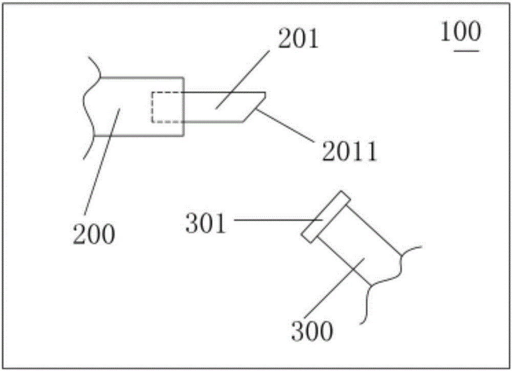
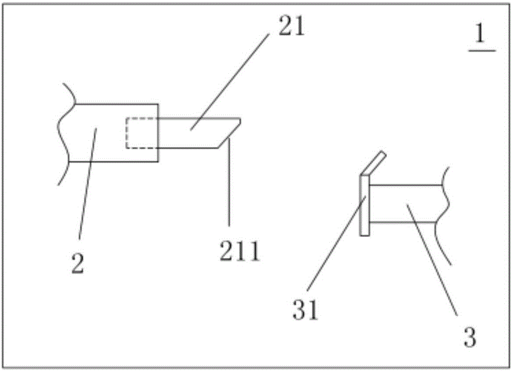
[0027] See Figure 2 to Figure 4 As shown, a non-horizontal direction insert device of a preferred embodiment is shown, wherein,

[0028] The machine tool 1 is an ordinary machine tool, the workpiece gripper 2 is equipped with a workpiece 21, the workpiece 21 has an inclined surface 211, and the insert gripper 3 is equipped with a non-horizontal insert 31, and both the workpiece gripper 2 and the insert gripper 3 are movable Ground installation (that is, adjustable) on the machine tool 1.

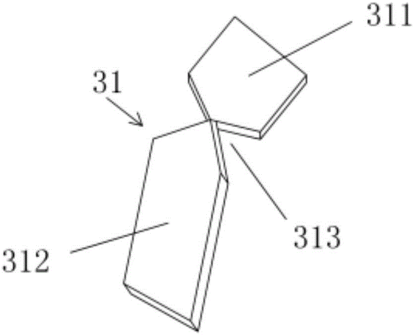
[0029] The insert gripper 3 can be set to move back and forth relative to the workpiece gripper 2. The insert gripper 3 sends the non-horizontal insert 31 to the workpiece gripper 2 and combines with the workpiece 21. The non-horizontal insert 31 is from top to bottom They are an inclined piece 311 and a vertical piece 312 respectively.

[0030] On the basis of the above, the present invention also has the following implementation modes, please continue to refer to Figure 2 to Figure 4 ...


PUM


Abstract

The invention discloses a non-horizontal-direction insert device and a working method thereof. The non-horizontal-direction insert device comprises a machine tool, a workpiece grab and an insert grab; a workpiece is assembled on the workpiece grab; a non-horizontal insert is assembled on the insert grab; the workpiece grab and the insert grab are movably installed on the machine tool; the insert grab is arranged in a mode of moving back and forth relative to the workpiece grab; and the non-horizontal insert comprises an inclined part and a vertical part from top to bottom. The non-horizontal insert is arranged to be of a structure with the upper part and the lower part, and the insert grab in the horizontal direction grabs the vertical part of the insert and moves horizontally to combine the insert with the workpiece. The problem that a grab of common equipment needs to be arranged obliquely and has a higher requirement for the installation space and assembly is solved, and the working efficiency of whole equipment is improved.

Description

technical field [0001] The invention relates to the technical field of electronic product assembly, in particular to a non-horizontal direction insert device and a working method thereof. Background technique [0002] During the production of electronic components, it is often encountered that the inserts on the components need to be set obliquely. The existing common production equipment 100 (such as figure 1 As shown) directly set the gripper 300 of the insert 301 obliquely relative to the gripper 200 of the workpiece 201, so that the insert 301 is parallel to the slope 2011 of the workpiece 201, extend the gripper to send the insert and combine with the workpiece. However, setting the two grippers obliquely requires a larger installation space, and at the same time, requires higher assembly requirements. Contents of the invention [0003] In order to solve the problem that existing equipment has high requirements for installation space and assembly, the invention provi...

Claims


Application Information

Patent Timeline
Patent Type & Authority Applications(China)
IPC IPC(8): B23P19/02
CPCB23P19/02
Inventor 申重行
Owner SHANGHAI GLOBAL PRECISION MOLD & PLASTICS
Why Eureka
Try Eureka