A high-efficiency bending machine

A bending machine, high-efficiency technology, applied to other manufacturing equipment/tools, manufacturing tools, etc., to achieve the effect of less manual participation, high degree of automation, and adjustment of bending angle

Active Publication Date: 2018-06-08
HUZHOU XINXING AUTOMOBILE PARTS
View PDF7 Cites 0 Cited by
  • Summary
  • Abstract
  • Description
  • Claims
  • Application Information

AI Technical Summary

Problems solved by technology

[0003] However, such a bending machine structure is simply a single bending operation of a steel pipe. With the development of modern industry, bending machine forming includes more processes, and there are higher requirements for bending efficiency.

Method used


Image

  • A high-efficiency bending machine
  • A high-efficiency bending machine
  • A high-efficiency bending machine

Examples


specific Embodiment approach

[0035] The present invention will be described in further detail below in conjunction with the accompanying drawings.

[0036] This specific embodiment is only an explanation of the present invention, and it is not a limitation of the present invention. Those skilled in the art can make modifications to this embodiment without creative contribution as required after reading this specification, but as long as they are within the rights of the present invention All claims are protected by patent law.

Embodiment 1

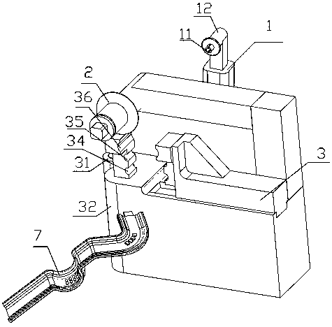
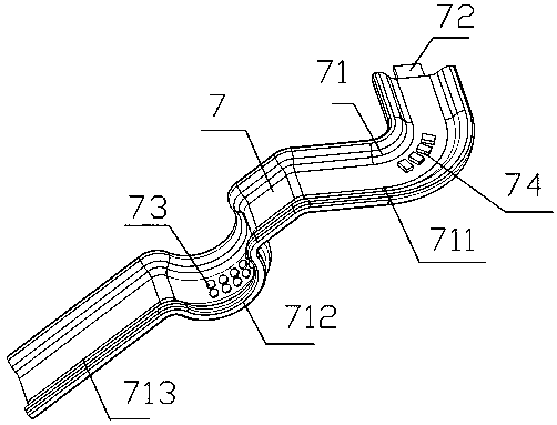
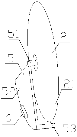
[0037] Example 1, such as figure 1 , figure 2 , image 3 and Figure 4 As shown, a high-efficiency bending machine includes a pipe inlet device 1 and a pipe outlet device 7, and also includes a clamping device 3 for clamping and bending steel pipes between the pipe inlet device 1 and the pipe outlet device 7 and for The cutting device 2 that cuts off the steel pipe after bending, the clamping device 3 includes a rotating shaft 31 extending in the vertical direction and a main frame 32 that is hinged to the rotating shaft and rotates in the horizontal direction, the main frame 32 includes a fixed block 1 and a Fixing block 2 close to or away from fixing block 1, fixed block 1 and fixing block 2 are provided with arc grooves, and the arc grooves cooperate with each other to form a clamping mouth 33 for clamping steel pipes, and clamping mouths 33 are provided with pipes for feeding steel pipes. The drilling device 4 for drilling, the main frame 32 can also move in the vertic...


PUM


Abstract

The invention relates to the field of elevator equipment, in particular to a high-efficiency bending machine. The present invention is achieved through the following technical solutions: a high-efficiency bending machine, which includes a pipe inlet device and a pipe outlet device, and also includes a pipe for clamping and bending a steel pipe located between the pipe inlet device and the pipe outlet device The pipe clamping device and the cutting device for cutting the bent steel pipe, the pipe clamping device includes a rotating shaft extending in the vertical direction and a main frame hinged to the rotating shaft and rotating in the horizontal direction, the The main frame includes a fixed block 1 and a fixed block 2 that can be close to or away from the fixed block 1. The fixed block 1 and the fixed block 2 are provided with arc grooves, and the arc grooves cooperate with each other to form a clamp for clamping steel pipes. Nozzle. The purpose of the present invention is to provide a high-efficiency bending machine with low manual participation in the whole process and a high degree of automation, which can meet multiple processing procedures.

Description

technical field [0001] The invention relates to the field of elevator equipment, in particular to a high-efficiency bending machine. Background technique [0002] Steel pipes are common components in industry and are used for supporting, connecting and rotating parts. During the processing of the steel pipe, the steel pipe needs to be bent. Traditional bending requires workers to manually bend, which is time-consuming and laborious, and the bending effect is also biased. There are also manufacturers who use the steel pipe bending machine published in the Chinese patent document CN 104550355 A as the notification number afterwards. It is bent into any arc. [0003] However, such a bending machine structure simply performs a single bending operation on a steel pipe. With the development of modern industry, bending machine forming involves more processes, and there are higher requirements for bending efficiency. Contents of the invention [0004] The purpose of the presen...

Claims


Application Information

Patent Timeline
Patent Type & Authority Patents(China)
IPC IPC(8): B23P23/04
CPCB23P23/04
Inventor 茹建军郭培芳
Owner HUZHOU XINXING AUTOMOBILE PARTS
Why Eureka
Try Eureka