Piston pump cylinder cup assembly device and assembly method

An assembly device and plunger pump technology, which is applied in the field of auto parts, can solve problems such as flanging and edge warping, and achieve the effects of high pass rate, simple and convenient operation, and strong practicability

Active Publication Date: 2018-07-17
ZHEJIANG ASIA PACIFIC MECHANICAL & ELECTRONICS
View PDF7 Cites 0 Cited by
  • Summary
  • Abstract
  • Description
  • Claims
  • Application Information

AI Technical Summary

Problems solved by technology

However, the above-mentioned leather cup assembly device is prone to warping and flanging after the leather cup is assembled in place.

Method used


Image

  • Piston pump cylinder cup assembly device and assembly method
  • Piston pump cylinder cup assembly device and assembly method
  • Piston pump cylinder cup assembly device and assembly method

Examples


Embodiment Construction

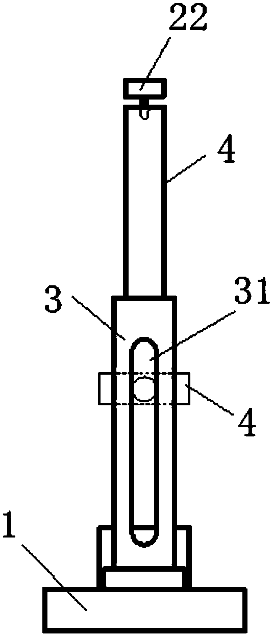
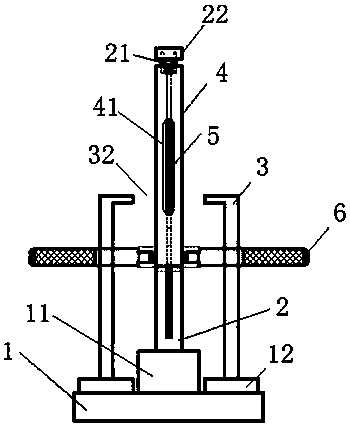
[0026] like figure 1 and figure 2 As shown, the piston pump cylinder body cup assembly device includes a fixed base plate 1, an installation mandrel 2 vertically installed on the fixed base plate 1, and a limit bracket 3 that is sheathed at the bottom of the installation mandrel. Wherein, the fixed base plate 1 is provided with a limit bracket block 11 to support the limit bracket 3, and also has an installation mandrel support block 12 supported on the bottom of the support and installation mandrel. The top of the installation mandrel 2 is provided with a cup installation groove for folding the cup into a U shape, and a protective sleeve 4 that can move up and down is nested on the radial outer side of the installation mandrel. At this time, the protection sleeve 4 is moved up and penetrated into the inner hole of the plunger pump cylinder. At this time, the protection sleeve 4 completely wraps the leather cup in the leather cup installation groove, so as to avoid the leath...


PUM


Abstract

The invention discloses a plunger pump cylinder leather cup assembly device and method. The plunger pump cylinder leather cup assembly device comprises a fixed bottom plate, an installation core rod perpendicularly installed on the fixed bottom plate, and a limiting support arranged outside the bottom of the installation core rod in a sleeving mode. A leather cup installation groove is formed in the top of the installation core rod, and a leather cup is folded into a U shape to be placed into the leather cup installation groove. The radial outer side of the installation core rod is provided with a protective sleeve capable of moving up and down in a nesting mode. The top of the limiting support is provided with a through hole, the limiting sleeve penetrates out of the through hole, and the open end of a plunger pump cylinder penetrates into the through hole. The top face of the limiting support limits steps of the open end of the plunger pump cylinder during downward pressing of the plunger pump cylinder. A movable lever pushing the leather cup into a leather cup groove of an inner hole of the plunger pump cylinder under the downward-pressing driving of the protective sleeve is arranged in the protective sleeve. Through the plunger pump cylinder leather cup assembly device and assembly method, one-time assembly in place rate of the leather cup is very high, and the edge warping and edge turning phenomena after in-place assembly of the leather cup can be avoided effectively.

Description

technical field [0001] The invention relates to the technology of auto parts, in particular to a piston pump cylinder body leather cup assembling device. Background technique [0002] In the prior art, the assembly device for the piston pump cylinder body cup has already solved how to install the cup into the piston pump cylinder body cup groove. For example, the Chinese invention patent with the publication number CN105500270A, on April 20, 2016, discloses an assembly tool and method for the cup of the piston pump cylinder cup assembly device, which includes, including a guide rod, and the guide rod can A guide sleeve that extends into the cylinder hole of the plunger pump cylinder and can pass through the center hole of the leather cup; a guide sleeve that can extend into the cylinder hole of the plunger pump cylinder, the inner diameter of the guide sleeve is larger than The outer diameter of the guide rod, after the guide sleeve is sleeved on the outside of the guide ro...

Claims


Application Information

Patent Timeline
Patent Type & Authority Patents(China)
IPC IPC(8): B25B27/02
CPCB25B27/02
Inventor 王智慧俞永尧吴新中夏燕峰
Owner ZHEJIANG ASIA PACIFIC MECHANICAL & ELECTRONICS
Why Eureka
Try Eureka