Paper compaction device for paper cutter

A technology of a pressing device and a paper cutter, which is applied in metal processing and other directions, can solve the problems of easy movement of paper, easy lifting of paper, damage to paper surface, etc., so as to improve cutting accuracy, increase market competitiveness, and prevent paper from being messed up. channeling effect

Inactive Publication Date: 2017-02-22
TAICANG XINHE PRINTING & PACKAGING
View PDF6 Cites 14 Cited by
  • Summary
  • Abstract
  • Description
  • Claims
  • Application Information

AI Technical Summary

Problems solved by technology

The existing pressing devices for paper often have the following problems: usually a single pressure pad is used for pressing. Due to the large size of the paper, one is that the paper is easy to move, and the other is that the unpressed paper is easy to warp. Affect the cutting accuracy of the paper, resulting in inconsistencies in the size of each paper to be cut
[0003] In addition, because the paper is subjected to a large shearing force during the cutting process of the paper cutter, the traditional paper cutter usually needs to press and fix the paper in order to ensure that the paper is firmly fixed, usually Cause damage to the surface of the paper, serious indentation, or even damage to the paper, resulting in waste of paper and increased costs
In addition, traditional compression devices usually use cylinders to control the pressure plate, while traditional cylinders mostly use telescopic methods to control the tightness of the pressure plate, which requires two-way power supply for telescopic and return strokes, and the pressure plate cannot automatically recover. The working process and control principle are more complicated , how to realize the automatic retraction of the cylinder without active retraction, simple structure and low cost has become a major problem to be solved by those skilled in the art

Method used


Image

  • Paper compaction device for paper cutter

Examples


Embodiment

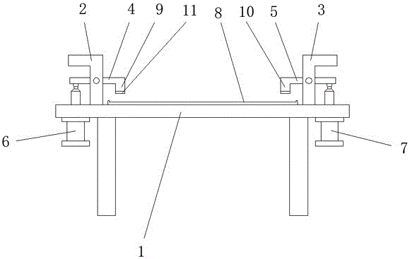
[0017] A paper pressing device for a paper cutter according to the present invention, such as figure 1 As shown, it includes: a platform 1, which is provided with a symmetrically distributed left bracket 2 and a right bracket 3 in an inverted "L" shape; the left bracket 2 is provided with a left pressure plate that can rotate around it 4. The corresponding right bracket 3 is provided with a rotatable right pressing plate 5; the left end of the left pressing plate 4 located outside the platform 1 is hinged to the piston rod of the left telescopic cylinder 6 fixed on the platform 1; One end of the right pressing plate 5 located on the outside of the platform 1 is hinged to the piston rod of the right telescopic cylinder 7 fixed on the platform 1; the platform 1 is provided with a cardboard 8; the cardboard 8 is in the shape of "concave" type; the left press plate 4 and the right press plate 5 are located at one end of the inner side of the stand 1 with a left press head 9 and a ...


PUM


Abstract

The invention discloses a paper compaction device for a paper cutter and belongs to the field of compaction mechanical equipment. The paper compaction device comprises a rack provided with a left support and a right support which are distributed symmetrically. The left support is provided with a left compaction plate capable of rotating round the left support. The right support corresponding to the left support is provided with a right compaction plate capable of rotating round the right support. The end, located on the outer side of the rack, of the left compaction plate is hinged to a piston rod of a left telescopic cylinder fixed to the rack. The end, located on the outer side of the rack, of the right compaction plate is hinged to a piston rod of a right telescopic cylinder fixed to the rack. The rack is provided with a paper supporting plate. The paper compaction device is simple in structure and reasonable in design. The bothway cylinders drive the compaction plates to clamp paper, firm fixation of the paper is ensured, the work efficiency is high, and very high market competitiveness is achieved.

Description

technical field [0001] The invention relates to the technical field of pressing mechanical equipment, in particular to a paper pressing device for a paper cutter. Background technique [0002] The production process of paper includes crushing, pulp washing, cooking, bleaching, papermaking and slitting of raw materials. Slitting is to cut the processed paper into smaller paper that meets the factory size requirements. When cutting paper, not only Cutting machine, and the paper should be pressed and positioned to prevent the size of the paper cut each time from being inconsistent. The existing pressing devices for paper often have the following problems: usually a single pressure pad is used for pressing. Due to the large size of the paper, one is that the paper is easy to move, and the other is that the unpressed paper is easy to warp. Affect the cutting accuracy of the paper, resulting in inconsistencies in the size of each paper to be cut. [0003] In addition, because th...

Claims


Application Information

Patent Timeline
Patent Type & Authority Applications(China)
IPC IPC(8): B26D7/02B26D7/01
CPCB26D7/025B26D7/015
Inventor 蒋冬艳
Owner TAICANG XINHE PRINTING & PACKAGING
Why Eureka
Try Eureka