
Torsion resistant pull rod of power assembly

A powertrain and anti-torsion tie rod technology, applied in the field of auto parts, can solve the problems that the torsion tie rod is difficult to install, affects normal use, and the inner tube of the torsion tie rod is equal, so as to achieve the effect of ensuring stability

Active Publication Date: 2017-02-22
NINGBO TUOPU GROUP CO LTD
View PDF8 Cites 4 Cited by
  • Summary
  • Abstract
  • Description
  • Claims
  • Application Information

AI Technical Summary

Problems solved by technology

In order to improve the performance of the torsion tie rod, sometimes it is necessary to install the torsion tie rod obliquely so that the upper surface of the torsion tie rod bracket and the horizontal plane form an inclined angle. The central axis of the inner tube in the connected bush is generally perpendicular to the upper end surface of the bracket. When one end of the bracket is installed at a certain inclination angle, the end surface of the inner tube in the bush will also be at a corresponding inclination angle to the horizontal plane. However, the installation surface on the body or subframe is generally flat, so that the inner tube of the torsion tie rod cannot be flattened with the body or subframe during installation, making it difficult to install the torsion tie rod to the body or subframe Even if the installation is complete, its installation stability is poor, affecting normal use

Method used


Image

  • Torsion resistant pull rod of power assembly
  • Torsion resistant pull rod of power assembly
  • Torsion resistant pull rod of power assembly

Examples


Embodiment 1

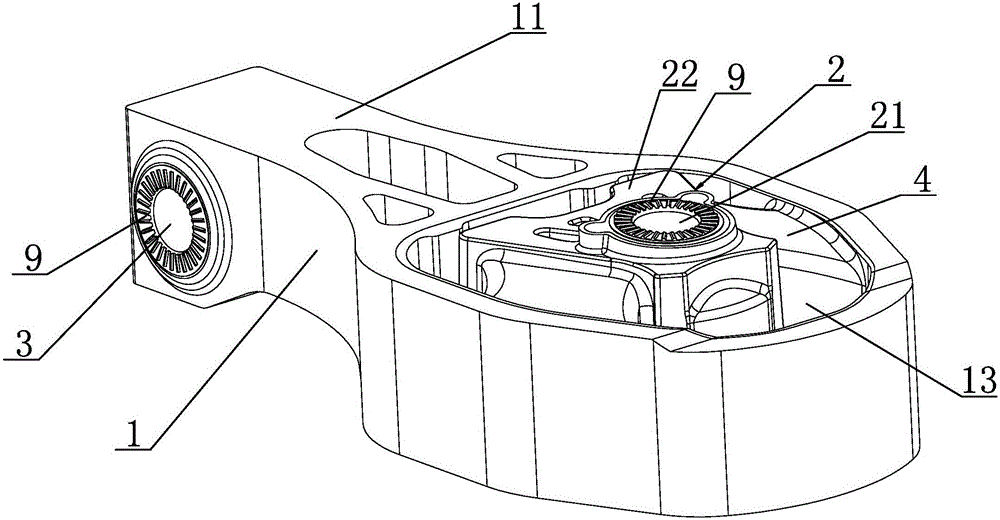
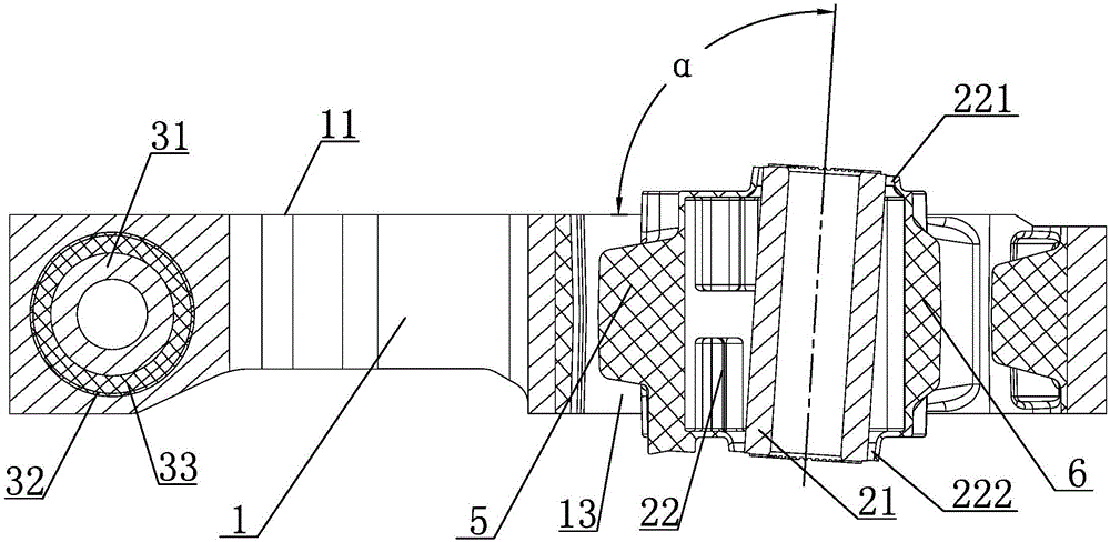
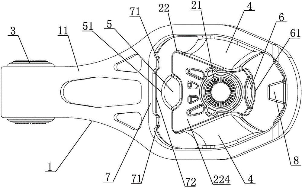
[0025] Embodiment one: if Figure 1 to Figure 6 As shown, a powertrain anti-torsion tie rod includes a tie rod bracket 1 and a large bush 2 and a small bush 3 respectively arranged at both ends of the tie rod bracket 1, the big bush 2 includes a large bush inner tube 21, and the small bush 3 includes a small bushing inner tube 31, the upper surface 11 of the tie rod bracket 1 is a flat end surface, the central axis of the small bushing inner tube 31 is parallel to the upper surface 11 of the tie rod bracket 1, and the central axis of the large bushing inner tube 21 is parallel to the An obtuse angle α is formed between the upper surfaces 11 of the tie rod bracket 1. When one end of the tie rod bracket 1 is connected to the powertrain through a small bush 3, an acute angle β is formed between the upper surface 11 of the tie rod bracket 1 and the horizontal plane. , the difference between obtuse angle α and acute angle β is 90°.

[0026] In this specific embodiment, one end of ...

Embodiment 2

[0036] Embodiment 2: other parts are the same as Embodiment 1, the difference is that the upper surface and the lower surface of the inner tube 21 of the large bush are provided with hobbing teeth 9, and the upper surface and the lower surface of the inner tube 31 of the small bush are provided with There are hobbing 9. Both the upper and lower surfaces of the large bush inner tube 21 and the small bush inner tube 31 are provided with hobbing teeth 9, which can effectively improve the friction coefficient between the parts and the installation interface, making the installation more stable.


PUM


Abstract

The invention discloses a torsion resistant pull rod of a power assembly. The torsion resistant pull rod comprises a pull rod bracket, a large liner bushing and a small liner bushing, wherein the large liner bushing and the small liner bushing are respectively arranged at two ends of the pull rod bracket; the large liner bushing comprises a large liner bushing inner pipe; and the small liner bushing comprises a small liner bushing inner pipe. The torsion resistant pull rod is characterized in that the upper surface of the pull rod bracket is a flat end surface; the central axis of the small liner bushing inner pipe is parallel to the upper surface of the pull rod bracket; an oblique obtuse angle is formed between the central axis of the large liner bushing inner pipe and the upper surface of the pull rod bracket; when one end of the pull rod bracket is connected with the power assembly through the small liner bushing, an oblique acute angle is formed between the upper surface of the pull rod bracket and a level surface; and the difference between the oblique obtuse angle and the oblique acute angle is 90 degrees. The torsion resistant pull rod disclosed by the invention has the advantages that after the pull rod bracket of the torsion resistant pull rod is mounted in a preset angle, the upper surface or the lower surface of the large liner bushing inner pipe can be mounted on a vehicle body or a sub vehicle frame in a flat clinging manner, so that the mounting stability and the whole using stability of the torsion resistant pull rod are guaranteed.

Description

technical field [0001] The invention relates to the field of auto parts, in particular to a power assembly anti-torsion tie rod. Background technique [0002] As a suspension component, anti-torsion tie rods have been widely used in powertrain vibration isolation systems, mainly for vehicles with transverse engines and front drive models. One end of the torsion tie rod is usually connected to the powertrain, and the other end is connected to the body or subframe. Its main function is to reduce the vibration of the engine from being transmitted to the body or subframe, and to limit the displacement of the powertrain in the X direction and around the Y direction. The twist angle of the shaft. [0003] A traditional torsion tie rod generally includes a bracket and two bushings respectively installed at both ends of the bracket, and the torsion tie rod is installed in the car through an inner tube provided in the bushing. In order to improve the performance of the torsion tie ...

Claims


Application Information

Patent Timeline
Patent Type & Authority Applications(China)
IPC IPC(8): B60K5/12
CPCB60K5/12
Inventor 韩文良贾勇何宋
Owner NINGBO TUOPU GROUP CO LTD
Learn More