A hot-press assembly device and a hot-press assembly method for a balance shaft

An assembly device and balance shaft technology, which is applied in the direction of workpiece clamping devices, metal processing, metal processing equipment, etc., can solve the problems of high error rate, many operators, and low clamping strength of the balance shaft body

Active Publication Date: 2016-06-22
SHANGHAI JIAOYUN AUTOMOTIVE POWER SYST
View PDF10 Cites 0 Cited by
  • Summary
  • Abstract
  • Description
  • Claims
  • Application Information

AI Technical Summary

Problems solved by technology

In the past, the hot-pressing assembly of the balance shaft was carried out manually. The disadvantages are: many operators, high work intensity, high error rate, poor processing quality of the balance shaft, and low production efficiency.
The reason for this situation is that during the hot press assembly process of the balance shaft, the manual operation cannot accurately control the installation angle of the balance shaft and the constant heating temperature of the sprocket, which makes it difficult to assemble the balance shaft parts
On the other hand, the unreasonable design of the balance shaft fixture also makes it difficult for the balance shaft to be positioned accurately in the balance shaft fixture, and the clamping strength of the balance shaft body in the balance shaft fixture is low

Method used


Image

  • A hot-press assembly device and a hot-press assembly method for a balance shaft
  • A hot-press assembly device and a hot-press assembly method for a balance shaft
  • A hot-press assembly device and a hot-press assembly method for a balance shaft

Examples


Embodiment Construction

[0055] see Figure 1 to Figure 17 In order to better understand the technical solution of the present invention, the inventors of the present invention will describe in detail below through specific embodiments in conjunction with the accompanying drawings:

[0056] A balance shaft hot-press assembly device of the present invention is used for hot-press assembling a balance shaft body and a sprocket, and the hot-press assembly becomes a balance shaft.

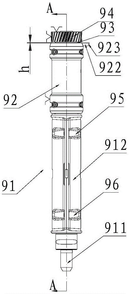
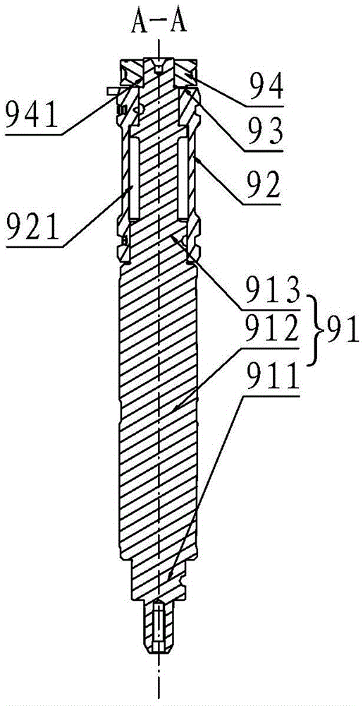
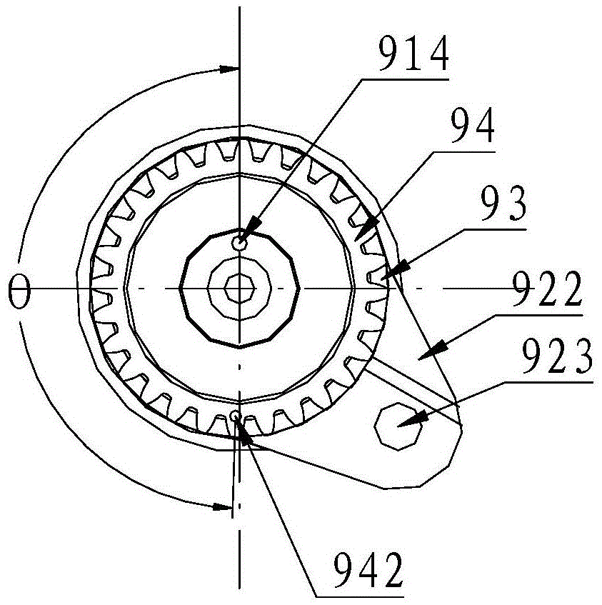
[0057] see Figure 1 to Figure 6 , the balance shaft used on the automobile, including a balance shaft body 91, a sleeve 92, a spacer 93 and a sprocket 94. Wherein, the balance shaft body 91 includes a shaft bottom 911 , a shaft middle 912 and a shaft top 913 . The cross-sectional shape of the shaft middle part 912 is a semicircle, because the cross-sectional shape of the shaft middle part 912 is a semicircle, so the outer peripheral surface of the shaft middle part 912 is surrounded by a curved surface and a plane, wherein t...


PUM


Abstract

The invention belongs to the field of automobile spare parts, and discloses a balance shaft hot-pressing assembling device. The balance shaft hot-pressing assembling device comprises a balance shaft conveying device and a hot press. The balance shaft hot-pressing assembling device is characterized in that a balance shaft clamp is arranged on the balance shaft conveying device, the balance shaft clamp comprises a lower positioning base, an upper positioning base and a clamp angle fixing assembly, the upper positioning base is fixed to the top face of the lower positioning base, a positioning error-proof through hole in the vertical direction is formed in the center of the upper positioning base, the clamp angle fixing assembly is located on the top face of the upper positioning base, the side, facing the positioning error-proof through hole, of the clamp angle fixing assembly is provided with a plane, the hot press comprises a loading weight shifting mechanism, a servo rotating mechanism, a servo weight shifting mechanism and a heating assembly, the servo rotating mechanism can drive chain wheels to rotate synchronously, and rotating positioning is carried out on the chain wheels. The balance shaft hot-pressing assembling device has the technical effect that the balance shaft can be accurately positioned inside the balance shaft clamp, so that the installation angle of the balance shaft is accurately controlled. The invention further discloses a balance shaft hot-pressing assembling method in the field of automobile spare parts, and the balance shaft hot-pressing assembling method can also achieve the technical effect.

Description

technical field [0001] The invention relates to a balance shaft hot-press assembly device and a hot-press assembly method in the field of auto parts. Background technique [0002] Among the vehicle NVH (Noise, Vibration, Harshness) parameters, vibration is undoubtedly the most critical element with the widest influence. It is not only one of the sources of noise, but also the chief culprit of high fuel consumption, and itself is an important factor affecting ride comfort. How to control the vibration, especially the vibration of the engine, has become the most serious problem faced by the vehicle NVH, and it is also an urgent problem to be solved. [0003] The planar arrangement of crankshafts commonly used in internal combustion engines makes the periodically changing excitation force and excitation torque in the engine cause severe vibration and even resonance. Practice has proved that by setting a balance shaft on the engine crankshaft or adding a balance weight, the fi...

Claims


Application Information

Patent Timeline
Patent Type & Authority Patents(China)
IPC IPC(8): B23P11/02B25B11/02
CPCB23P11/025B25B11/02
Inventor 杨佳磊殷俊东罗为杨立坚
Owner SHANGHAI JIAOYUN AUTOMOTIVE POWER SYST
Why Eureka
Try Eureka