Automatic bar loading device

An automatic feeding and bar material technology, applied in the direction of transportation and packaging, conveyor objects, etc., can solve the problems of labor consumption, poor safety, low efficiency, etc., and achieve the effect of solving time-consuming

Inactive Publication Date: 2017-02-22
SHANGHAI JINGZHI IND CO LTD
View PDF7 Cites 11 Cited by
  • Summary
  • Abstract
  • Description
  • Claims
  • Application Information

AI Technical Summary

Problems solved by technology

[0004] The purpose of the present invention is to propose an automatic bar loading device to solve the problems of time-consuming, labor-intensive, low efficiency, poor feeding stability and poor safety in the feeding process, and at the same time solve the problem of one-time multi-bar feeding. problem

Method used


Image

  • Automatic bar loading device
  • Automatic bar loading device
  • Automatic bar loading device

Examples


Embodiment Construction

[0026] In order to enable those skilled in the art to better understand the technical solution of the present invention, the technical solution of the present invention will be further described below in conjunction with the accompanying drawings and through specific implementation methods.

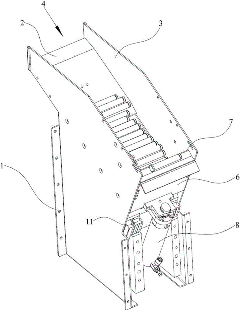
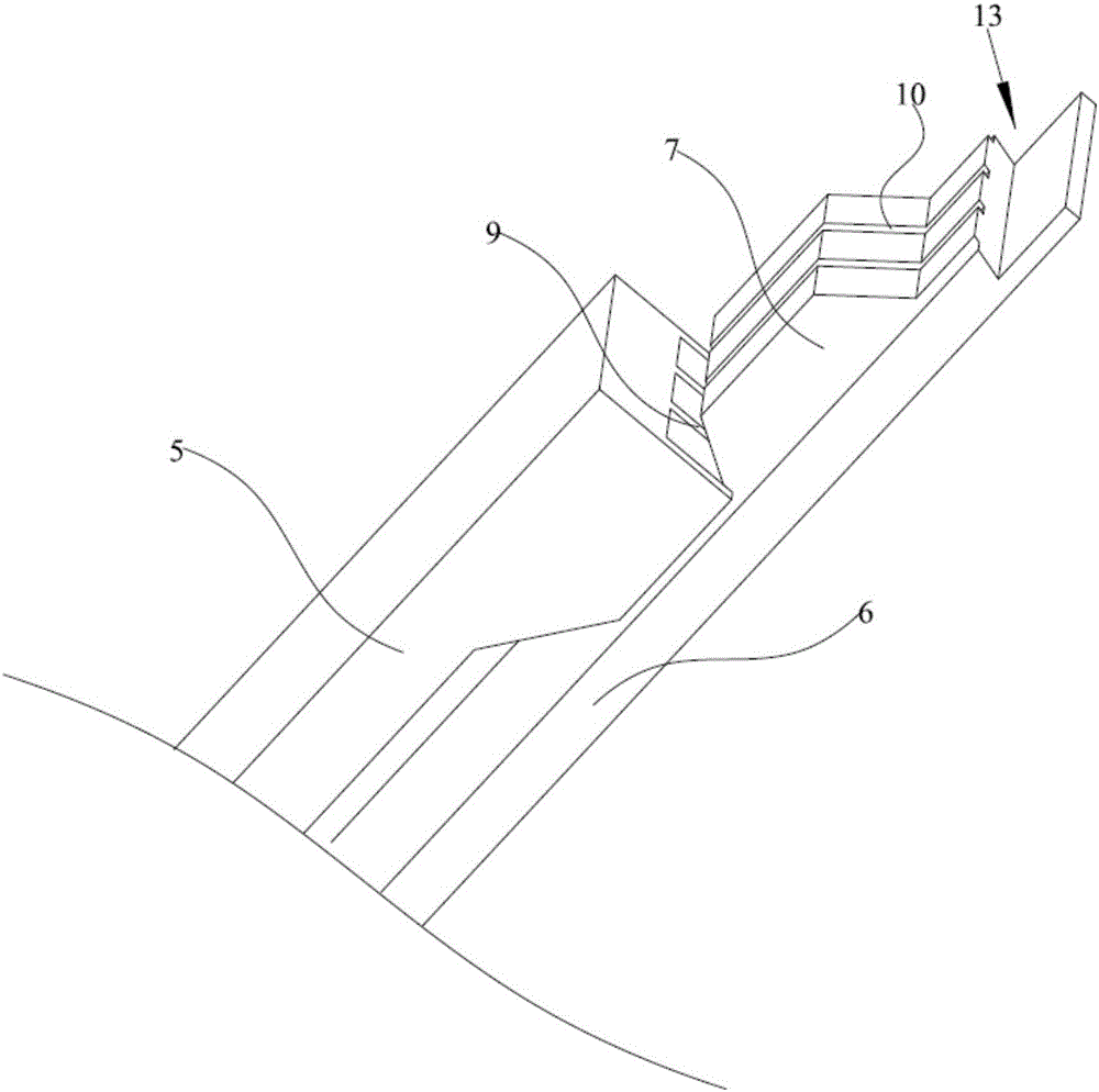
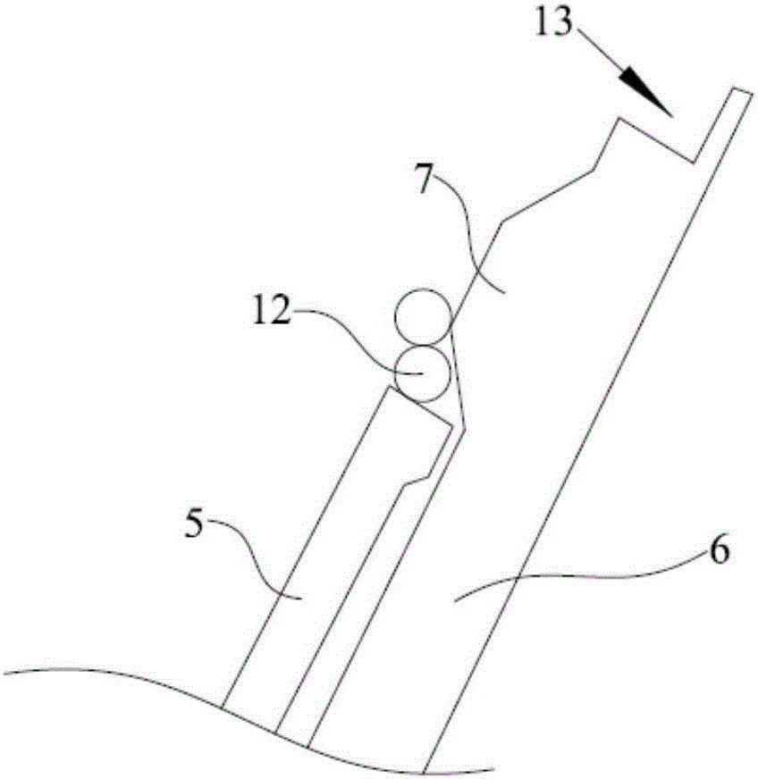
[0027] like Figure 1-Figure 5 As shown, this specific embodiment provides a kind of bar stock 12 automatic feeding device, comprises frame 1, is provided with feeding channel 4 on frame 1, and one end of feeding channel 4 is provided with pusher plate 5 obliquely, pusher plate 5 The side far away from the feeding channel 4 is provided with a material blocking plate 6 in parallel, and the pushing plate 5 is connected with a drive mechanism 8. Driven by the driving mechanism 8, the pushing plate 5 slides along the material blocking plate 6, and on the material blocking plate 6 A boss 7 is provided, and the boss 7 matches the top surface of the pushing plate 5, so that when the pushing plat...


PUM


Abstract

The invention relates to the technical field of automatic loading, in particular to an automatic bar loading device. The automatic bar loading device comprises a machine frame, wherein a feeding channel is formed in the machine frame; a pushing plate is obliquely arranged at one end of the feeding channel; a stopping plate is arranged in parallel on the side, far away from the feeding channel, of the pushing plate; the pushing plate is connected with a driving mechanism, and is driven by the driving mechanism to slide along the stopping plate; a lug boss is arranged on the stopping plate, and is matched with the top surface of the pushing plate to ensure that only one bar is reserved on the top surface of the pushing plate when the pushing plate moves to the lug boss. According to the automatic bar loading device, the lug boss is arranged on the stopping plate, and is matched with the top surface of the pushing plate to ensure that only one bar is reserved on the top surface of the pushing plate when the pushing plate moves to the lug boss, so that a function of sequentially loading individual bars can be realized. In addition, the bars are automatically loaded, so that the problems of time consuming, labor consuming, low efficiency and poor loading stability and safety in a manual loading process can be solved.

Description

technical field [0001] The invention relates to the technical field of automatic feeding, in particular to an automatic feeding device for bar materials. Background technique [0002] In order to ensure the subsequent processing of the bar material and realize its feeding one by one, it is necessary to place the bar material on the trough. Usually, the bar is manually clamped and placed on the trough. However, manually placing the bars in the trough will make the entire feeding process time-consuming, labor-intensive, inefficient, and difficult to guarantee the stability and safety of feeding. [0003] In addition, the patent No. CN201310299674.1 describes an automatic bar material feeding device for a heating furnace, including a material storage box and a material guide groove. The material storage box includes a material storage cavity, and the bottom plate of the material storage cavity is inclined; The material guide chute is installed on the outer wall of the material...

Claims


Application Information

Patent Timeline
Patent Type & Authority Applications(China)
IPC IPC(8): B65G47/82B65G47/26
CPCB65G47/82B65G47/26
Inventor 鲁金林刘建武裴明丰邓树强汪伟
Owner SHANGHAI JINGZHI IND CO LTD
Why Eureka
Try Eureka