Screw drill

A screw drilling tool and screw technology, which is applied to drilling equipment, earthwork drilling, and driving devices for drilling in boreholes. long life effect

Inactive Publication Date: 2017-02-22
钟文楚
0 Cites 0 Cited by

AI-Extracted Technical Summary

Problems solved by technology

[0005] The disadvantages of this screw drilling tool are: the internal meshing gear is not wear-resistant in the mud environment containing solid particles, and the service life is short; when ...

Abstract

The invention provides an all-metal screw drill. Usually, an all-metal screw drill is composed of a multi-screw hydraulic motor assembly, a transmission shaft assembly and an inside engaged gear, the common inside engaged gear is prone to abrasion in a drilling fluid environment, and the gear is prone to being disengaged to cause fall-into-well accidents after a shell is fractured. An inside engaged gear of the screw drill is made from solid carbide and designed to be a straight gear and is capable of being machined through a linear cutting machining method; an anti-falling ring or an anti-falling disc is mounted on the gear to prevent gear disengagement; and the all-metal screw drill can effectively prevent the fall-into-well accidents caused by shell fracturing, and the service life of the inside engaged gear is long.

Application Domain

Borehole drives

Technology Topic

Fall into wellEngineering +6

Image

  • Screw drill
  • Screw drill
  • Screw drill

Examples

  • Experimental program(2)

Example Embodiment

[0018] Example 1:
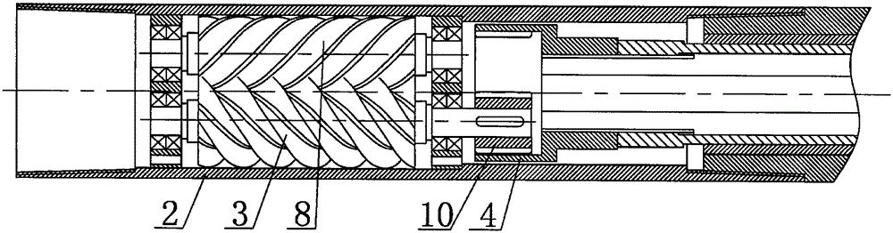
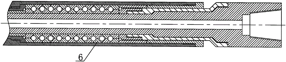
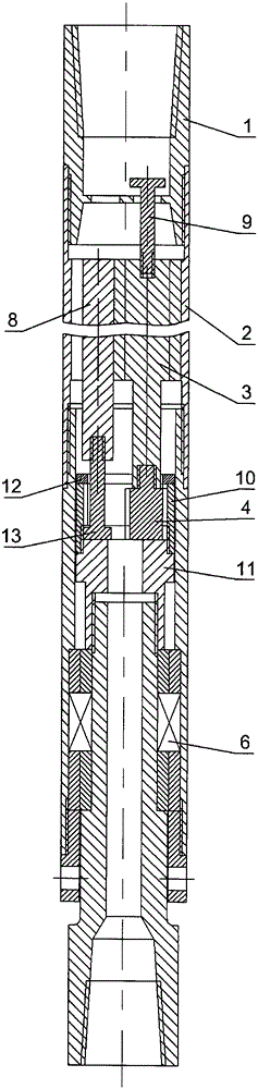
[0019] Such as image 3 As shown, the screw drilling tool is composed of an anti-dropping joint 1, an anti-dropping rod 9, a motor assembly, a transmission shaft assembly and an intermediate connecting part. In order to improve the service life of the gears, the material of the internal gear 10 and the external gear 4 is designed to be solid cemented carbide, but because the hardness of cemented carbide is too high, it can only be processed by wire cutting. In order to facilitate the processing of gears by the wire cutting processing equipment, the internal gear 10 and the external gear 4 are designed as straight-toothed cylindrical gears, so that the tooth profile can be processed by the wire cutting method. In order to prevent damage to other parts of the gear except the tooth profile during wire cutting, the gear is designed such that the outer contour of the external gear 4 except the tooth profile is within the cylindrical surface of the tooth root, and the internal gear 10 is inside the other parts except the tooth profile. The contour is outside the cylindrical surface of the tooth root.
[0020] As the screw drill tool occasionally breaks the shell during the drilling process, which will cause the parts below the fracture to fall into the well, so there is a water cap 11 at the lower end of the internal gear 10, and the upper end of the internal gear 10 and the water cap 11 A groove is formed. The inner diameter of the groove is larger than the diameter of the addendum circle of the internal gear 10. The lower end of the screw 8 other than the output shaft is equipped with a shaft extension 13, and the shaft extension 13 is inserted into the internal gear 10. The shape is a stepped shaft, and the lower end step is embedded in the groove. If the motor is always a twin-screw motor, only one output shaft other than the lower end of the screw 8 is equipped with a shaft extension 13; if the motor is always three or more screw motors, it is necessary to have multiple output shafts other than the lower end of the screw 8 Axis extension 13. The upper end of the internal gear is equipped with an anti-dropping ring, and the inner hole size of the anti-dropping ring is smaller than the outer contour size generated by the lower end of the external gear 4 and the shaft extension 13. If the screw housing is broken, the relative position of the screw axis will not change, so the inner and outer gears will not disengage. Since the upper end of the output shaft 3 is equipped with an anti-dropping rod 9, the upper end of the anti-dropping rod 9 is smaller than the inner hole of the anti-dropping connector 1, so even if the housing below the anti-dropping connector 1 is broken, the parts below the fracture will pass through the connection The integrated transmission shaft, internal and external gears, output shaft 3 and anti-dropping rod 9 are firmly hung on the anti-dropping joint 1 so as to avoid the occurrence of falling accidents.
[0021] When the motor is running, the screw will generate radial force and axial force. The inner hole of the motor housing 2 is in direct contact with the screw to bear the radial force, the axial force of the output shaft 3 is borne by the external gear 4 and the water cap 11 directly, and the screw 8 other than the output shaft passes through the shaft extension 13 at the lower end and the inner The upper end of the gear or the upper end of the water cap directly contacts to bear the axial force.

Example Embodiment

[0022] Example 2:
[0023] Such as Figure 4 As shown, the screw drill is composed of the anti-drop joint 1, the anti-drop rod 9, the motor assembly, the transmission shaft assembly and the intermediate connecting parts. The axis of the motor assembly and the transmission shaft assembly forms a small angle, the bending point At the internal gear. In order to improve the service life of the gears, the material of the internal gear 15 and the external gear 16 is designed to be solid cemented carbide, but due to the high hardness of the cemented carbide, it can only be processed by wire cutting. In order to facilitate the processing of gears by the wire cutting processing equipment, the internal gear 15 and the external gear 16 are designed as straight-tooth bevel gears, so that the tooth profile can be processed by the wire cutting method. In order to prevent damage to other parts of the gear except the tooth profile during wire cutting, the gear is designed such that the outer contour of the external gear 16 except the tooth profile is within the tooth root conical surface, and the internal gear 15 is inside the other parts except the tooth profile. The contour is outside the tooth root cone.
[0024] Due to the occasional shell fracture accident of the screw drilling tool during the drilling process, which will cause the parts below the fracture to fall into the well, so the lower end of the internal gear 15 is equipped with a water cap 11, an internal gear 15 and a water cap 11 A groove is formed at the upper end. The inner diameter of the groove is larger than the diameter of the addendum circle of the lower end surface of the internal gear 15. The lower end of the screw 8 except for one or more output shafts is equipped with a shaft extension 13, which is inserted into the internal gear 15. The shape of the extension 13 is a stepped shaft, and the lower end step is embedded in the groove. If the motor is always a twin-screw motor, only one output shaft other than the lower end of the screw 8 is equipped with a shaft extension 13; if the motor is always three or more screw motors, it is necessary to have multiple output shafts other than the lower end of the screw 8 Axis extension 13. The lower end of the external gear 16 is equipped with an anti-dropping disk 14 which is embedded in the groove, so that the diameter of the addendum of the internal gear 15 is smaller than the outer contour size formed by the step at the lower end of the shaft extension 13 and the anti-dropping disk 14. If the screw housing is broken, the relative position of the screw axis will not change, so the inner and outer gears will not disengage. Since the upper end of the output shaft 3 is equipped with an anti-dropping rod 9, the upper end of the anti-dropping rod 9 is smaller than the inner hole of the anti-dropping connector 1, so even if the housing below the anti-dropping connector 1 is broken, the parts below the fracture will pass through the connection The integrated transmission shaft, internal and external gears, output shaft 3 and anti-dropping rod 9 are firmly hung on the anti-dropping joint 1 so as to avoid the occurrence of falling accidents.
[0025] When the motor is running, the screw will generate radial force and axial force. The lower end of the motor housing 2 is equipped with a thrust plate 7. The inner hole of the motor housing 2 is in direct contact with the screw to bear the radial force. The step surface of all the screws and the upper end surface of the thrust plate 7 directly contact to form a sliding thrust bearing, and all the axial forces of the screw are borne by the thrust plate.

PUM

no PUM

Description & Claims & Application Information

We can also present the details of the Description, Claims and Application information to help users get a comprehensive understanding of the technical details of the patent, such as background art, summary of invention, brief description of drawings, description of embodiments, and other original content. On the other hand, users can also determine the specific scope of protection of the technology through the list of claims; as well as understand the changes in the life cycle of the technology with the presentation of the patent timeline. Login to view more.

Similar technology patents

Glomerocryst cubic boron nitride composite sheet and preparation method for same

ActiveCN103158287AExtended service lifeIncreased depth of cut
Owner:ZHENGZHOU BERLT HARD MATERIALS

Sleep assistance mattress

ActiveCN106842979AReduce data processing pressureExtended service life
Owner:DONGGUAN UNIV OF TECH

Recovering and using technology of water in electroplating

Owner:海宁市海整整流器有限公司

Classification and recommendation of technical efficacy words

Why Eureka
Try Eureka