Eureka AIR delivers breakthrough ideas for toughest innovation challenges, trusted by R&D personnel around the world.

Draught fan assembly and domestic electric appliance with draught fan assembly

A technology of household electrical appliances and components, applied in the direction of machines/engines, pump components, mechanical equipment, etc., can solve the problems of small air volume, high noise of fan components, and easy deformation of the impeller, so as to optimize the scale and strength, improve the air volume, The effect of improving reliability

Active Publication Date: 2017-02-22
GUANGDONG MIDEA WHITE GOODS TECH INNOVATION CENT CO LTD +1
View PDF7 Cites 0 Cited by
  • Summary
  • Abstract
  • Description
  • Claims
  • Application Information

AI Technical Summary

Problems solved by technology

[0003] The air volume blown by the fan assembly in the related art is small and the noise is large
Although the air supply volume can be increased by increasing the speed of the motor, this leads to greater noise of the fan assembly, and the high speed of the motor increases the loss of the motor, increases the cost, and reduces the reliability and safety
In addition, when the air volume is not enough, a large-diameter impeller is sometimes used to solve the problem. This will not only increase the volume of the fan component itself, but also increase the overall volume of the household appliances. Moreover, considering that the large-diameter impeller is easy to deform under high temperature, this There are higher requirements for the material of the large-diameter impeller, and stricter requirements for the adjustment of dynamic balance, resulting in an increase in material costs and installation costs

Method used


Image

  • Draught fan assembly and domestic electric appliance with draught fan assembly
  • Draught fan assembly and domestic electric appliance with draught fan assembly
  • Draught fan assembly and domestic electric appliance with draught fan assembly

Examples


Embodiment Construction

[0030] Embodiments of the invention are described in detail below, examples of which are illustrated in the accompanying drawings. The embodiments described below by referring to the figures are exemplary and are intended to explain the present invention and should not be construed as limiting the present invention.

[0031] In describing the present invention, it is to be understood that the terms "center", "length", "width", "thickness", "upper", "lower", "front", "rear", etc. indicate an orientation or The positional relationship is based on the orientation or positional relationship shown in the drawings, which is only for the convenience of describing the present invention and simplifying the description, rather than indicating or implying that the referred device or element must have a specific orientation, be constructed and operated in a specific orientation, Therefore, it should not be construed as limiting the invention.

[0032] In addition, the terms "first" and "...


PUM


Abstract

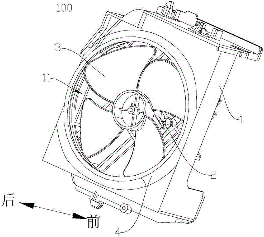
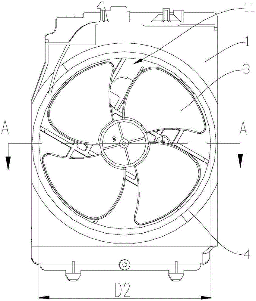
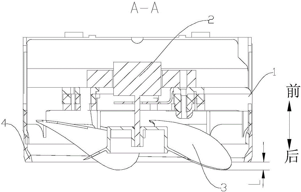
The invention discloses a draught fan assembly and a domestic electric appliance with the draught fan assembly. The draught fan assembly comprises a motor support, a motor, impellers and a flow collecting structure. A through hole is formed in the motor support. The motor is fixed to the front side of the motor support. The impellers are located in the through hole and connected with a motor shaft of the motor. The flow collecting structure is arranged on the motor support and corresponds to the through hole. The rear end face of the flow collecting structure is located on the rear side of the rear surface of the motor support. The height of the impellers is B, and the distance between the rear edges of the impellers and the rear end face of the flow collecting structure is L, wherein L is larger than or equal to 5% of B and smaller than or equal to 30% of B. According to the draught fan assembly, the air discharging amount of the fan assembly is better improved, and noise is lowered.

Description

technical field [0001] The invention relates to the technical field of household electrical appliances, in particular to a fan assembly and a household electrical appliance having the same. Background technique [0002] Generally, a fan is usually provided in a household appliance to facilitate heat dissipation of the household appliance. [0003] The air volume blown by the fan assembly in the related art is small and the noise is large. Although the air supply volume can be increased by increasing the speed of the motor, this leads to greater noise of the fan assembly, and the high speed of the motor increases the loss of the motor, increases the cost, and reduces the reliability and safety. In addition, when the air volume is not enough, a large-diameter impeller is sometimes used to solve the problem. This will not only increase the volume of the fan component itself, but also increase the overall volume of the household appliances. Moreover, considering that the large-...

Claims


Application Information

Patent Timeline
IPC IPC(8): F04D25/08F04D29/54
CPCF04D25/08F04D29/541
Inventor 张冀喆李长明陈茂顺张辉李忠华
Owner GUANGDONG MIDEA WHITE GOODS TECH INNOVATION CENT CO LTD
Why Eureka
Eureka Blog
Learn More