
Energy saving clutch

A clutch and assembly technology, applied in the field of auto parts, can solve the problems of high work intensity of drivers, low degree of automation, wear and tear of parts, etc., and achieve the effect of good fuel saving, lightening labor intensity and reducing wear and tear.

Active Publication Date: 2018-07-13
RES INST OF ZHEJIANG UNIV TAIZHOU
View PDF9 Cites 0 Cited by
  • Summary
  • Abstract
  • Description
  • Claims
  • Application Information

AI Technical Summary

Problems solved by technology

[0003] The purpose of the present invention is to solve the technical problems of frequent stepping on clutches of conventional automobiles, severe wear between parts, high fuel consumption, low degree of automation, and high work intensity of the driver

Method used


Image

  • Energy saving clutch
  • Energy saving clutch
  • Energy saving clutch

Examples


Embodiment Construction

[0030] The present invention will be further described below in conjunction with the accompanying drawings and specific embodiments.

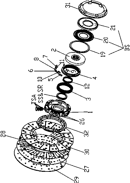
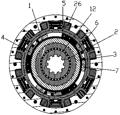
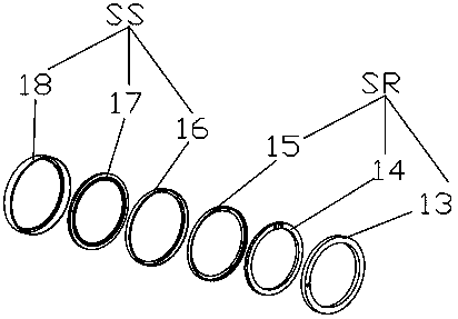
[0031] Such as Figure 1-7 As shown, the energy-saving clutch of the present invention includes a coaxial driving disc 1, a passive disc 2, a first helical sleeve 3, a second helical sleeve 4 and an active steel plate 27, and the middle part of the space formed by the driving disc 1 and the passive disc 2 is installed There is a first helical sleeve 3, the left helical key set in the inner diameter direction of the first helical sleeve 3 is slidingly matched with the left helical key set on the driving disk 1, and the right helical key arranged radially outside the first helical sleeve 3 is in contact with the second helical sleeve 4. The right screw key arranged radially inside is slidingly fitted; one end surface of the first spiral sleeve 3 is provided with a ratchet 301, and the corresponding end surface of the passive disc 2 is provided wi...


PUM


Abstract

The invention discloses an energy saving clutch. A first spiral sleeve is mounted in space formed by the middle parts of a driving disc and a driven disc; a left spiral key radially arranged in the first spiral sleeve is slidingly matched with a left spiral key arranged on the driving disc; a right spiral key radially arranged out of the first spiral sleeve is slidingly matched with a right spiral key radially arranged in the second spiral sleeve; a ratchet arranged to one end surface of the driven disc by the first spiral sleeve is corresponding to a ratchet arranged on the middle end surface of the driven disc for joining in acceleration; a positioning block, a stress block, a slope block, a roller, a stress spring and a power slow transfer spring are respectively mounted in a groove radially formed out of the second spiral sleeve; a bearing is mounted radially at one end in the driving disc to the driven disc, and a small oil seal base is radially arranged in the other end; one surface, in the direction of a clutch pressing disc, of a driving steel plate is connected with a waveform spring plate and a first friction plate; and the other surface of the driving steel plate is connected with a second friction plate. The energy saving clutch has an automatic clutching function, and is excellent in energy saving effect.

Description

technical field [0001] The invention relates to an automobile part, in particular to an energy-saving clutch. Background technique [0002] With the development of the times and the progress of society, the energy available for automobiles has gradually decreased and become increasingly tense, leading to rising oil prices, and the use of energy-saving and environmentally friendly automobiles has become a global consensus. However, the existing ordinary automobile clutches are frequently stepped on during operation, the wear and tear between the parts is serious, and the fuel consumption is high; . Based on the above situation, research and development of energy-saving clutch is imminent. Contents of the invention [0003] The purpose of the present invention is to solve the technical problems of frequent stepping on clutches of conventional automobiles, severe wear between parts, high fuel consumption, low degree of automation, and high work intensity of drivers in conve...

Claims


Application Information

Patent Timeline
Patent Type & Authority Patents(China)
IPC IPC(8): F16D41/06F16D41/066F16D21/08
CPCF16D21/08F16D41/06F16D41/066
Inventor 王文臣王维锐
Owner RES INST OF ZHEJIANG UNIV TAIZHOU
Learn More