
Electronic cigarette lighter and vehicle-mounted electronic cigarette lighting equipment

An electronic cigarette lighting and contact technology, which is applied to lighting and heating equipment, combustion ignition, incandescent ignition, etc. Effect

Active Publication Date: 2017-02-22
湖南酷伯新晶电子科技有限公司
View PDF7 Cites 3 Cited by
  • Summary
  • Abstract
  • Description
  • Claims
  • Application Information

AI Technical Summary

Problems solved by technology

[0003] The object of the present invention is to provide an electronic cigarette lighter and a vehicle-mounted electronic cigarette lighter device, which aims at at least partially solving the problem of the existing cigarette lighter, the heating wire is exposed outside the housing, the service life is short, and the usability is poor. technical problem

Method used


Image

  • Electronic cigarette lighter and vehicle-mounted electronic cigarette lighting equipment
  • Electronic cigarette lighter and vehicle-mounted electronic cigarette lighting equipment
  • Electronic cigarette lighter and vehicle-mounted electronic cigarette lighting equipment

Examples


no. 1 example

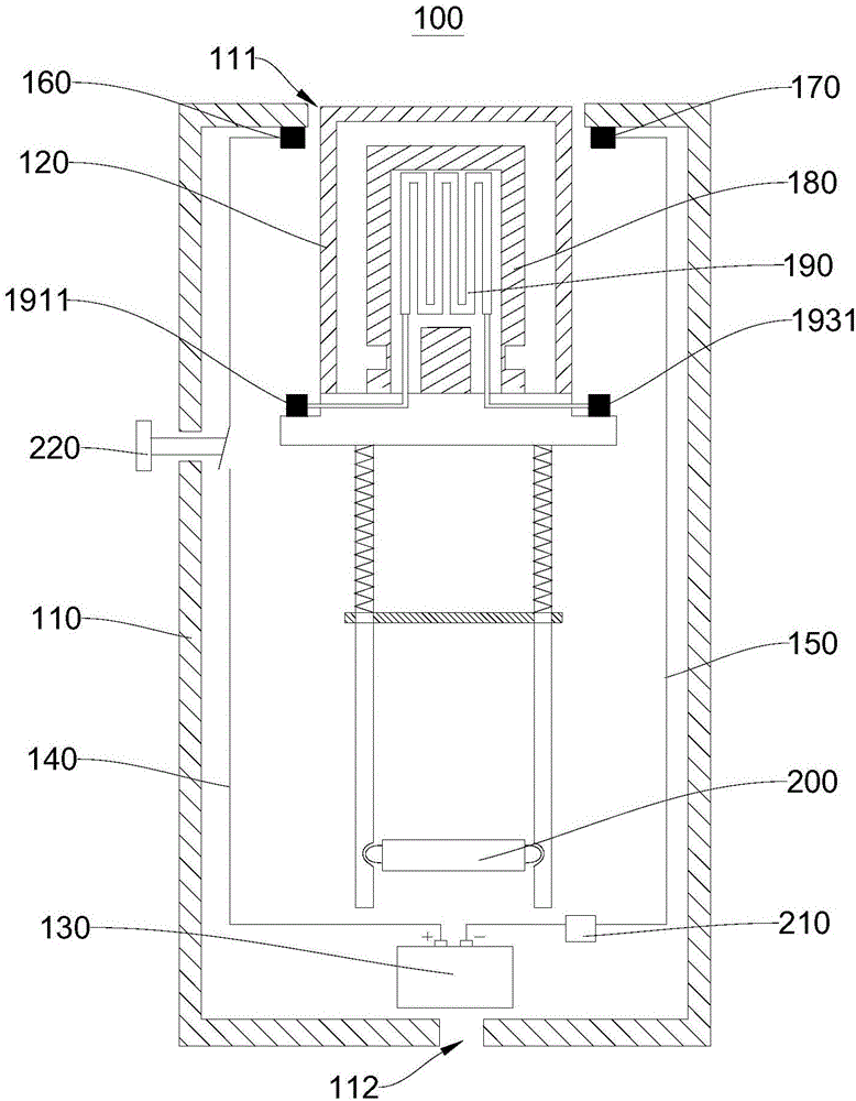
[0036] figure 1 For the schematic structural diagram of the electronic cigarette lighter 100 provided in the first embodiment of the present invention when not in use, please refer tofigure 1 . It should be noted that, in all the drawings, reference numerals with arrows refer to imaginary structures, such as holes, grooves, cavities, etc., and reference numerals without arrows refer to solid structures.

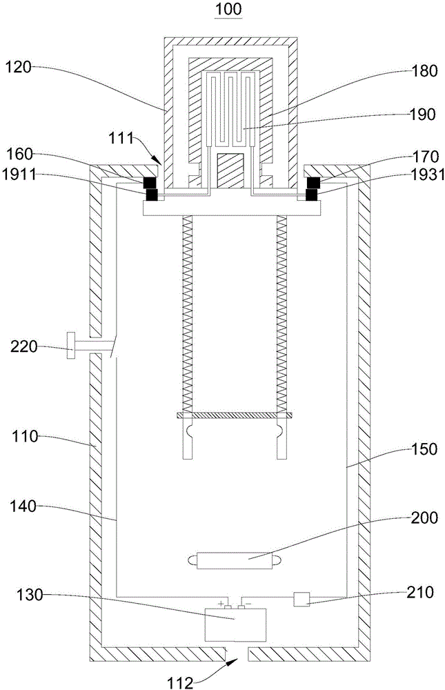
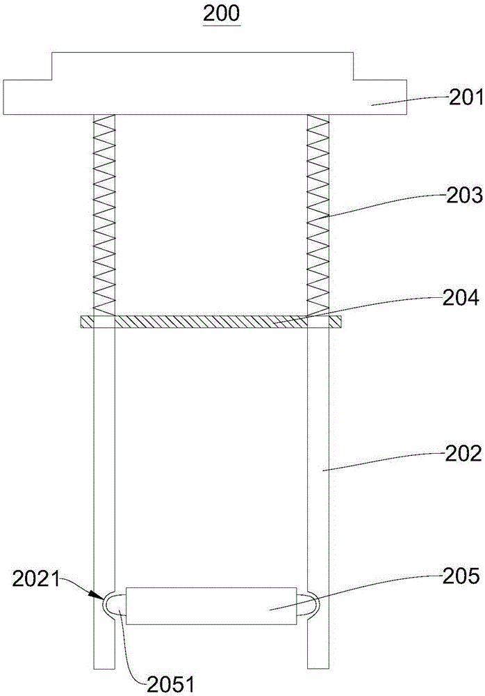
[0037] The electronic cigarette lighter 100 provided in this embodiment includes a housing 110 , a protective cover 120 , a power supply 130 , a positive lead 140 , a negative lead 150 , a positive contact 160 , a negative contact 170 , a glass heating cover 180 , and a heating wire 190 , elastic support switch 200, circuit overload circuit breaker 210 and main switch 220.

[0038] Power supply 130 , circuit overload breaker 210 , positive lead 140 , negative lead 150 , positive contact 160 , negative contact 170 , and spring mount switch 200 are disposed inside housing 110 ...

no. 2 example

[0067] This embodiment provides a vehicle-mounted electronic cigarette lighter device, which includes a mount and the electronic cigarette lighter 100 in the first embodiment. The electronic cigarette lighter 100 is installed on the mounting base, and the mounting base is used to be installed on the vehicle body.

[0068] The vehicle-mounted electronic cigarette lighter device provided by the present invention adopts the above-mentioned electronic cigarette lighter 100, which not only makes it more convenient for passengers or drivers to light cigarettes in the vehicle, but also does not generate more smoke, and does not cause excessive smoke at the vehicle-mounted electronic point of view. Tobacco, tobacco leaves and other sundries remain in the tobacco equipment, keeping the environment clean and tidy.


PUM


Abstract

The invention provides an electronic cigarette lighter and vehicle-mounted electronic cigarette lighting equipment and relates to the technical field of electronic cigarette lighting. The electronic cigarette lighter comprises a shell, a power supply, a positive pole guide wire, a negative pole guide wire, a positive pole contact, a negative pole contact, a glass heating cover, a heating wire and an elastic support switch. The glass heating cover and the heating wire are mounted on the elastic support switch. The heating wire is arranged in the glass heating cover. The elastic support switch controls the glass heating cover and the heating wire to stretch out of an open hole and makes the first end of the heating wire to make contact with the positive pole contact and the second end of the heating wire to make contact with the negative pole contact; or the elastic support switch controls the glass heating cover and the heating wire to contract into the open hole and makes the first end of the heating wire to be separated from the positive pole contact and the second end of the heating wire to be separated from the negative pole contact. According to the electronic cigarette lighter, the heating wire is not exposed outside, the service life of the heating wire is prolonged, and the inside of the electronic cigarette lighter is made neat.

Description

technical field [0001] The invention relates to the technical field of electronic cigarette lighting, in particular to an electronic cigarette lighter and a vehicle-mounted electronic cigarette lighting device. Background technique [0002] In the existing cigarette lighter, the heating wire is exposed outside the casing, so that the cigarette can directly contact with the heating wire, thereby lighting the cigarette end. However, making the cigarette directly in contact with the heating wire will cause shredded tobacco, tobacco leaves and other sundries to fall into the cigarette lighter. Combustion will produce too much smoke, and the soot produced after combustion will also spread inside the cigarette lighter, making the inside of the cigarette lighter not only untidy and unsightly, but also may affect the performance of the cigarette lighter. In addition, the heating wire is exposed outside the casing, and the heating wire is easily oxidized at high temperature, which s...

Claims


Application Information

Patent Timeline
Patent Type & Authority Applications(China)
IPC IPC(8): F23Q7/24B60N3/14
CPCF23Q7/24B60N3/14
Inventor 赵杰芳赵银芳李勇李超唐群红赵敏
Owner 湖南酷伯新晶电子科技有限公司
Learn More