Supercharge Your Innovation With Domain-Expert AI Agents!

Centralized control system and method for machine room air conditioner unit group

A centralized control system, computer room air-conditioning technology, applied in heating and ventilation control systems, heating and ventilation safety systems, applications, etc., can solve problems such as large power consumption, rapid fluctuations in return air temperature, and uneven heating and cooling in computer room areas, and achieve Effects of improving reliability and improving overall operating efficiency

Inactive Publication Date: 2017-02-22
NANJING PERFECT WORLD TECH CO LTD
View PDF5 Cites 2 Cited by
  • Summary
  • Abstract
  • Description
  • Claims
  • Application Information

AI Technical Summary

Problems solved by technology

[0003] 1. Each air conditioner operates independently, but the actual area layout load is uneven, resulting in uneven cooling and heating in the computer room area
The overall indoor ambient temperature fluctuates widely
[0004] 2. The local wind short circuit causes the return air temperature to fluctuate rapidly after the air conditioner is turned on, and the equipment starts and stops frequently
[0005] 3. Lack of overall scheduling, the number of on-duty aircraft cannot be adjusted in time when the load changes, resulting in excessive power consumption of on-duty aircraft
[0006] 4. Each air conditioner operates independently, and the difference in individual parameters may lead to internal friction in the air conditioner room (some heating / humidity, some cooling / dehumidification), consuming a lot of power in vain

Method used


Image

  • Centralized control system and method for machine room air conditioner unit group
  • Centralized control system and method for machine room air conditioner unit group
  • Centralized control system and method for machine room air conditioner unit group

Examples


Embodiment Construction

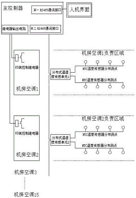
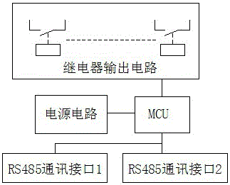
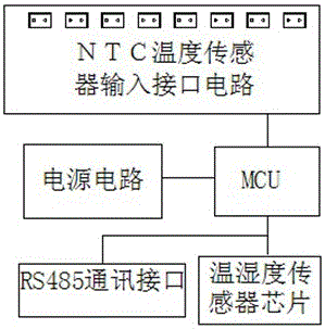
[0019] Such as figure 1 As shown, a centralized control system for computer room air conditioner groups includes a main controller, distributed temperature and humidity sensing units, terminal control relays, and a human-machine interface, such as figure 2 As shown, the main controller is an embedded system based on single-chip microcomputer, including power supply circuit, MCU (single-chip microcomputer), first and second RS485 communication circuits, relay output circuit, MCU and power supply circuit, two-way RS485 communication circuit, relay output circuit connection. Such as image 3 As shown, the distributed temperature and humidity sensing unit is an embedded system based on a single-chip microcomputer, including a power supply circuit, an MCU (single-chip microcomputer), a RS485 communication circuit, a circuit with an 8-way NTC temperature sensor input interface, and a built-in high-precision temperature sensor. The humidity sensor chip and the MCU are respectivel...


PUM


Abstract

The invention relates to a centralized control system and method for a machine room air conditioner unit group. The centralized control system comprises a master controller, a man-machine interface, distributed temperature and humidity sensing units and terminal control relays. One distributed temperature and humidity sensing unit is correspondingly arranged in an area of which each air conditioner in the machine room air conditioner unit group takes charge. The master controller comprises two RS485 communication circuits, the first RS485 communication circuit is connected with the man-machine interface, the second RS485 communication circuit is a communication host connector, and the first RS485 communication circuit and the second RS485 communication circuit are connected with the distributed temperature and humidity sensing units through communication correspondingly. Intermediate relays are arranged in a master controller plate of the master controller. Each intermediate relay is correspondingly connected with one terminal control relay. Each terminal control relay is arranged in a corresponding air conditioner distribution box. The master controller integrally dispatches starting and stopping running of all air conditioners in a machine room, the temperature field of the machine room is controlled in a balanced manner, the overall running efficiency is improved, and coordination control is conducted for achieving the purpose of energy saving.

Description

technical field [0001] The invention relates to an air conditioner regulating device, in particular to a centralized control system and method for a group of air conditioners in a machine room. Background technique [0002] In a typical communication equipment room, the power consumption of the air conditioner reaches more than 40% of the power consumption of all equipment, which is a large power consumer. The computer room air conditioner group is the key object of energy saving and emission reduction in the computer room. However, the overall operating efficiency of the computer room, especially the old computer room air-conditioning group that does not have collaborative control capabilities, is low, resulting in a significant increase in power consumption. The main manifestations are: [0003] 1. Each air conditioner operates independently, but the actual area layout load is uneven, resulting in uneven cooling and heating in the computer room area. The overall indoor a...

Claims


Application Information

Patent Timeline
Patent Type & Authority Applications(China)
IPC IPC(8): F24F11/02
Inventor 邹亮平
Owner NANJING PERFECT WORLD TECH CO LTD
Features
  • R&D
  • Intellectual Property
  • Life Sciences
  • Materials
  • Tech Scout
  • Unparalleled Data Quality
  • Higher Quality Content
  • 60% Fewer Hallucinations
Learn More