
LED patch bracket

A technology of LED patch and LED chip, applied in the direction of electrical components, circuits, semiconductor devices, etc., can solve the problems of light loss, affecting brightness, and easy damage

Inactive Publication Date: 2017-02-22
李鹤荣
View PDF7 Cites 1 Cited by
  • Summary
  • Abstract
  • Description
  • Claims
  • Application Information

AI Technical Summary

Problems solved by technology

[0002] The corners of the bowls of the LED patch brackets on the market are generally in the form of straight lines and flat angles, resulting in a large loss of brightness at the corners, reducing light efficiency, and the shape of straight lines and flat angles affects the uniformity of light emission.
In addition, the light-emitting angle of the LED patch brackets currently on the market is small, resulting in a narrow illuminated area, which affects the light-emitting effect.
In addition, the substrate at the bottom of the bracket body currently on the market is generally an integral structure. In addition to fixing the LED chip, the substrate also plays a role in heat conduction and heat dissipation. When multiple LED chips are fixed on the integral substrate, it is not conducive to the heat dissipation of the LED chip. Moreover, when multiple LED chips need to be connected in series or in parallel, the leads can only be soldered to the electrodes of the chips, which is easy to cause damage to the LED chips due to the secondary welding power and excessive pressure.
In addition, the width of the bottom of the bowl of the LED patch bracket on the market is relatively wide and the length is short. When the LED chip is fixed to the bottom of the bowl, part of the light emitted by the LED chip will irradiate the bottom of the bowl, resulting in light loss. When fixing multiple LED chips, it is easy to cause light loss due to overlap of light emission and affect the brightness. Moreover, the LED chip bracket with a relatively wide width and a short length has average folding resistance and is prone to damage.

Method used


Image

  • LED patch bracket
  • LED patch bracket
  • LED patch bracket

Examples


Embodiment Construction

[0019] It should be understood that the specific embodiments described here are only used to explain the present invention, not to limit the present invention.

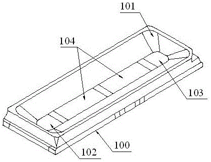
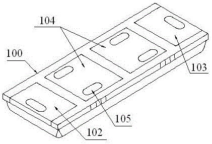
[0020] refer to Figure 1 to Figure 5 , an embodiment of an LED patch bracket of the present invention is proposed, which includes a bracket body 100 with a bowl inside, and a number of LED chips can be installed on the bottom of the bowl of the bracket body 100, and installed in the bowl behind the LED chip Can be filled with fluorescent glue.

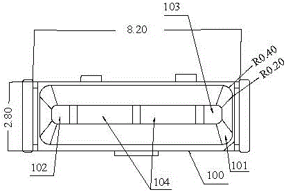
[0021] The inner surface of the cup of the bracket body 100 has an inverted trapezoidal structure. The corners of the inverted trapezoidal structure are set as arc-shaped corners 101 which are beneficial to improve light efficiency and luminous uniformity. The corners of the bowls of the LED patch brackets on the market are generally in the form of straight lines and flat angles, resulting in a large loss of brightness at the corners, reducing light efficiency, and the shap...


PUM


Abstract

The invention discloses an LED patch bracket, which comprises a bracket body, wherein a bowl is arranged in the bracket body; a plurality of LED chips can be arranged at the bottom of the bowl of the bracket body and the bowl can be filled with fluorescent glue after the LED chips are arranged; the inner side surface of the bowl of the bracket body is of an inverted trapezoidal structure; the range of the included angle between two transverse sides of the inverted trapezoidal structure is 108-110 degrees; the range of the included angle between two vertical sides of the inverted trapezoidal structure is 135-137 degrees; a plurality of insulated and isolated substrates are fixedly arranged at the bottom of the bracket body; the substrate comprises a positive substrate, a negative substrate and a plurality of chip substrates capable of installing the LED chips arranged between the positive substrate and the negative substrate; the positive substrate and the negative substrate are arranged at two ends of the bottom of the bracket body; the back surfaces of the substrates all are provided with bonding pads capable of welding leads; and the LED chips are connected in series or in parallel through the leads welded on the bonding pads.

Description

technical field [0001] The invention relates to the technical field of LED lamp bead brackets, in particular to an LED patch bracket. Background technique [0002] The corners of the bowls of the LED patch brackets on the market are generally in the form of straight lines and flat angles, resulting in a large loss of brightness at the corners, reducing light efficiency, and the shape of straight lines and flat angles affects the uniformity of light emission. In addition, the light-emitting angle of the LED patch brackets currently on the market is small, resulting in a narrow illuminated area, which affects the light-emitting effect. In addition, the substrate at the bottom of the bracket body currently on the market is generally an integral structure. In addition to fixing the LED chip, the substrate also plays a role in heat conduction and heat dissipation. When multiple LED chips are fixed on the integral substrate, it is not conducive to the heat dissipation of the LED c...

Claims


Application Information

Patent Timeline
Patent Type & Authority Applications(China)
IPC IPC(8): H01L33/48H01L33/54H01L33/62H01L33/60H01L33/64
CPCH01L33/486H01L33/54H01L33/60H01L33/62H01L33/64
Inventor 李鹤荣
Owner 李鹤荣
Learn More