Positive and negative pressure-relief battery core

A technology of positive and negative electrodes and battery cells, which is applied in the field of positive and negative electrode discharge cores, can solve the problems of affecting the battery cells, the explosion of the battery cells, the bursting of the battery cells, etc., and achieves the effects of reasonable design, convenient operation and simple structure.

Pending Publication Date: 2017-02-22
苏州索尔智行新能源科技有限公司
View PDF10 Cites 0 Cited by
  • Summary
  • Abstract
  • Description
  • Claims
  • Application Information

AI Technical Summary

Problems solved by technology

[0002] Ordinary batteries will explode when they are overcharged and the temperature is too high. When a normal battery explodes, it explodes from the positive side, and there are no other explosion protection measures on the negative side. It is easy to cause the overall burst of the battery to affect other nearby batteries.

Method used


Image

  • Positive and negative pressure-relief battery core
  • Positive and negative pressure-relief battery core
  • Positive and negative pressure-relief battery core

Examples


Embodiment 1

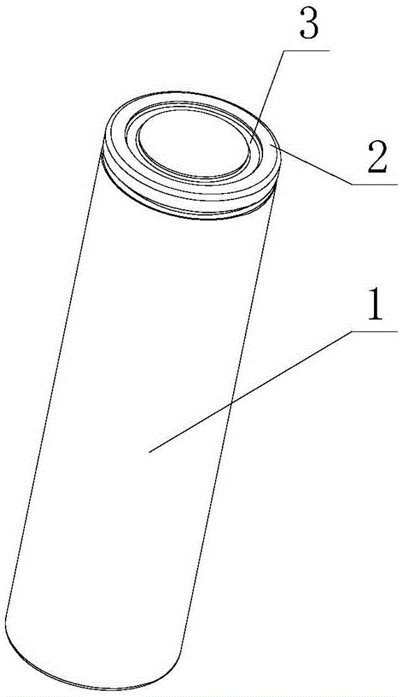
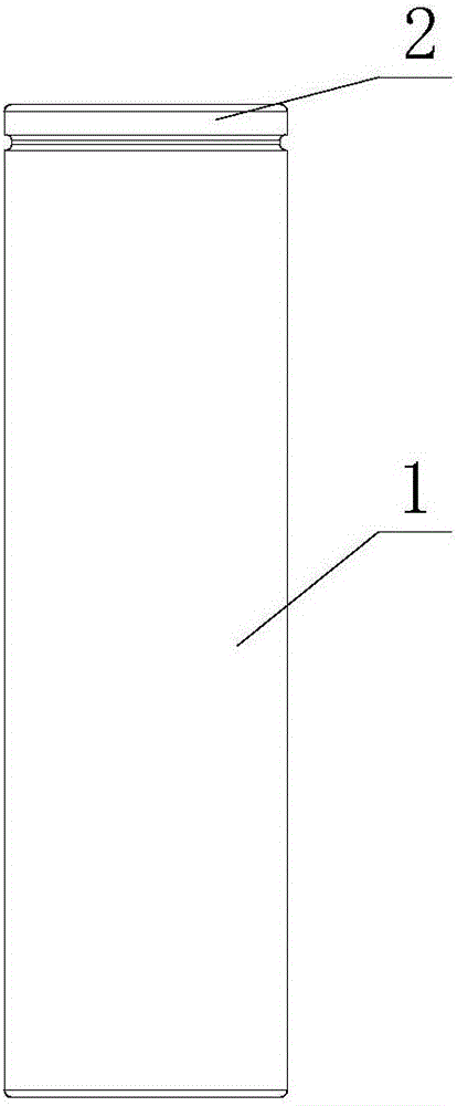
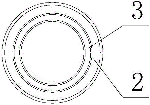
[0022] like figure 1 , figure 2 , image 3 , Figure 4 The shown positive and negative pressure relief cells include a cell body 1, one end of the cell body 1 is provided with a positive end face 2, the other end of the cell body 1 is provided with a negative end face 4, and the positive end face 2 is provided with a positive groove 3. The negative electrode surface 4 is provided with a negative electrode groove 5 engraved by a laser. The depth of the negative electrode groove 5 is 0.08-0.15 mm, preferably 0.1 mm. The negative electrode groove 5 is C-shaped.

Embodiment 2

[0024] like figure 1 , figure 2 , image 3 , Figure 5 and Image 6 The shown positive and negative pressure relief cells include a cell body 1, one end of the cell body 1 is provided with a positive end face 2, the other end of the cell body 1 is provided with a negative end face 4, and the positive end face 2 is provided with a positive groove 3. The negative electrode surface 4 is provided with a negative electrode groove 5 engraved by a laser. The depth of the negative electrode groove 5 is 0.15 mm, and the negative electrode groove 5 is a combination of a C shape and a straight line.

Embodiment 3

[0026] like figure 1 , figure 2 , image 3 , Figure 7 The shown positive and negative pressure relief cells include a cell body 1, one end of the cell body 1 is provided with a positive end face 2, the other end of the cell body 1 is provided with a negative end face 4, and the positive end face 2 is provided with a positive groove 3. The negative electrode surface 4 is provided with a negative electrode groove 5 engraved by a laser. The depth of the negative electrode groove 5 is 0.08mm, and the negative electrode groove 5 is Y-shaped.

[0027] The present invention is simple in structure, reasonable in design, and easy to operate. Because the thickness of the negative groove of the cell is smaller than that of its periphery, it is easy to burst the negative groove when the battery explodes; similarly, the thickness ratio of the positive groove is The thickness of its periphery is small, and when the cell explodes, it is easy to burst the positive groove, so the heat can...


PUM

PropertyMeasurementUnit
Depthaaaaaaaaaa
Depthaaaaaaaaaa
Depthaaaaaaaaaa

Abstract

The invention discloses a positive and negative pressure-relief battery core. The positive and negative pressure-relief battery core comprises a battery core main body, wherein a positive end surface is arranged at one end of the battery core main body; a negative end surface is arranged at the other end of the battery core main body; a positive groove is arranged in the positive end surface; a negative groove is arranged in the negative end surface; and the depth of the negative groove is 0.08-0.15mm. The positive and negative pressure-relief battery core is simple in structure, reasonable in design and convenient to operate. The thickness of the negative groove of the battery core is smaller than that of the periphery and the negative groove is easily exploded when the battery core explodes, so that heat can be discharged from two ends of the positive end surface and the negative end surface, the heat can be quickly discharged and adjacent other battery cores are not easily affected.

Description

technical field [0001] The invention relates to the technical field of battery cells, in particular to a positive and negative electrode pressure-relieving battery cell. Background technique [0002] Ordinary batteries will explode when they are overcharged or overheated. When a normal battery explodes, it explodes from the positive side, and there are no other explosion protection measures on the negative side. It is easy to cause the overall burst of the battery to affect other nearby batteries. . Contents of the invention [0003] The technical problem to be solved by the present invention is: to overcome the deficiencies of the prior art, and provide a positive and negative pressure-relieving cell, which can quickly release heat. [0004] The technical solution adopted by the present invention to solve the technical problem is: a positive and negative pressure relief cell, including a cell body, one end of the cell body is provided with a positive end surface, and the...

Claims


Application Information

Patent Timeline
IPC IPC(8): H01M2/30H01M50/30H01M50/548H01M50/553
CPCH01M50/543Y02E60/10
Inventor 王乾钱科季伟源
Owner 苏州索尔智行新能源科技有限公司
Why Eureka
Try Eureka