Coupling structure of filter port and common port coupling structure of waveguide duplexer

A technology of coupling structure and common port, applied in the field of electronic communication

Active Publication Date: 2020-10-27
PIVOTONE COMM TECH
View PDF10 Cites 0 Cited by
  • Summary
  • Abstract
  • Description
  • Claims
  • Application Information

AI Technical Summary

Problems solved by technology

[0005] The purpose of the present invention is to provide a coupling structure of a filter port and a common port coupling structure of a waveguide duplexer designed using a TM01 mode for the defects of the mode design of the existing TE10 mode

Method used


Image

  • Coupling structure of filter port and common port coupling structure of waveguide duplexer
  • Coupling structure of filter port and common port coupling structure of waveguide duplexer
  • Coupling structure of filter port and common port coupling structure of waveguide duplexer

Examples


Embodiment Construction

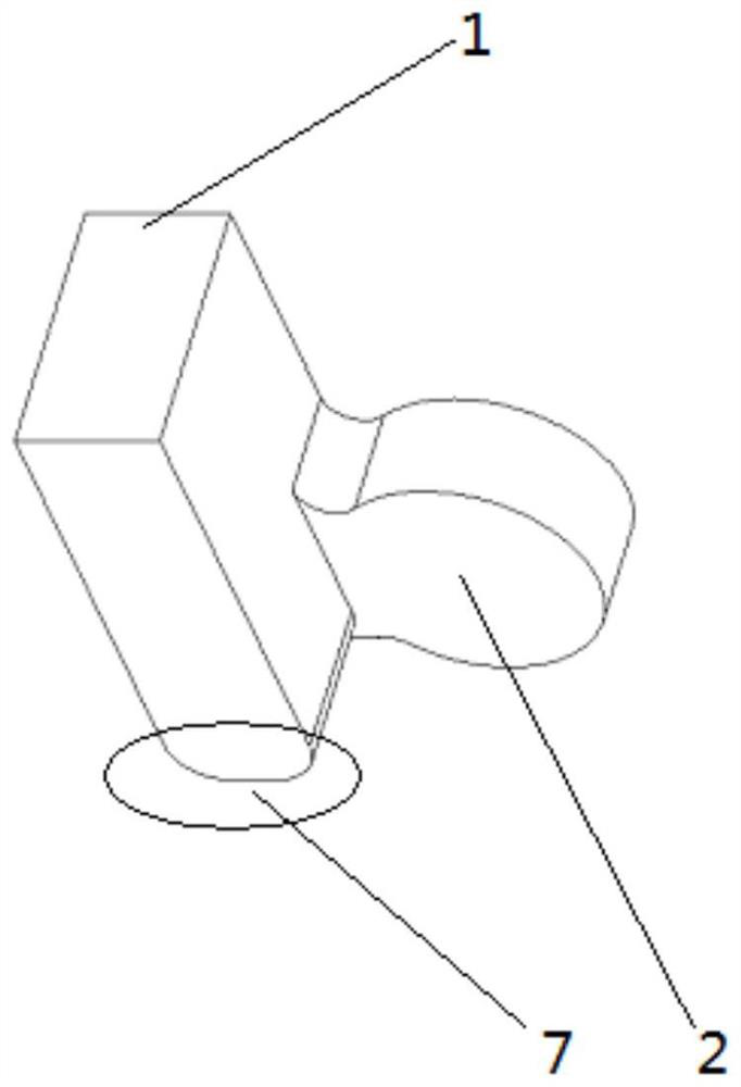
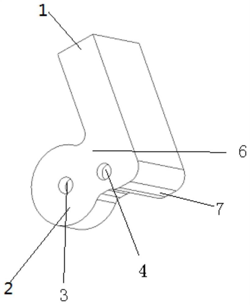
[0017] figure 1 , 2 It is a port coupling structure in the form of waveguide mode conversion of waveguide filter, which converts the TE10 mode of the waveguide into the TM01 mode of the waveguide. It includes a rectangular waveguide 1 and a resonant cavity 2 connected with the waveguide filter and the rectangular waveguide 1 . There is a frequency tuning screw 3 inside the resonant cavity 2 to tune the resonant frequency of the resonant cavity 2, and a coupling tuning screw 4 is provided at the coupling window 6 from the rectangular waveguide 1 to the resonant cavity 2 to tune the coupling amount. On the upper part of the rectangular waveguide end face 7, it can be as figure 1 , 2 As shown, there is no step, and a step can also be added here to increase the coupling amount by increasing the step, which is determined according to the required coupling amount. Adjusting the diameter of the resonant cavity 2 can adjust the central resonant frequency point of the coupling port...


PUM


Abstract

The invention discloses a filter port coupling structure and a waveguide duplexer common port coupling structure. TE10 mode of a waveguide is converted into TH01 mode of the waveguide. The problems of large size and high cost can be well solved. Compared with traditional TE10 mode designed products, the product designed using new techniques is less than 1 / 4 as large as the original products, the cost is greatly reduced, no great impact is caused upon the performance, and large-scale production is more facilitated. By using the novel coupling structure, the waveguide filter / waveguide duplexer design is more flexible.

Description

technical field [0001] The invention belongs to the technical field of electronic communication, in particular to a coupling structure of a filter port and a common port coupling structure of a waveguide duplexer. Background technique [0002] Waveguide filters and waveguide duplexers have large power capacity and low insertion loss, and are widely used in various wireless communication, radar, electronic countermeasure and other equipment. [0003] With the development of wireless communication, the demand for waveguide filters and waveguide duplexers is increasing, and cost reduction has become a new requirement for waveguide filters / duplexers. [0004] Since the waveguide filter duplexer needs to be connected by a waveguide flange, the waveguide flange occupies a relatively large space and is not flexible enough, which easily leads to a large size of the waveguide filter / duplexer and high cost. If the traditional design method of the waveguide filter is adopted, that is,...

Claims


Application Information

Patent Timeline
Patent Type & Authority Patents(China)
IPC IPC(8): H01P1/207H01P1/208
CPCH01P1/207H01P1/208
Inventor 江顺喜周方平殷实梁国春项显赵媛媛林身平
Owner PIVOTONE COMM TECH
Why Eureka
Try Eureka