
Wireless charging device and electronic candle lamp with same

A wireless charging and circuit technology, applied in the direction of circuit devices, battery circuit devices, components of lighting devices, etc., can solve problems such as complex circuit structure, wear and tear of charging interface, single function, etc.

Pending Publication Date: 2017-02-22
江阴旺达电子有限公司
View PDF4 Cites 6 Cited by
  • Summary
  • Abstract
  • Description
  • Claims
  • Application Information

AI Technical Summary

Problems solved by technology

[0003] Since the advent of electronic candles, their use safety, convenience, energy saving, and environmental protection are being liked by more and more people, especially in European and American countries, and gradually have a tendency to replace traditional life-fire stick candles. Electronic candles in the prior art are generally The charging interface is used for charging. This charging method will cause serious wear and tear on the charging interface after a long time, and finally lead to failure to charge. Most of the electronic candles on the market use a single switch to open the mode, which has a single function and is not competitive
[0004] By combining the above two technologies, a wireless charging electronic candle is produced, but the wireless charging electronic candle in the prior art is usually only charged in a one-to-one manner, that is, one transmitting antenna corresponds to one receiving antenna, such as CN 203836826 U, discloses a multi-induction wireless charging candle. When using this technology, multiple electronic candles cannot be charged at the same time, such as US2007 / 0223217A1. Although this technology discloses a one-to-many charging method, the principle of its application is still A transmitting antenna corresponds to a receiving antenna, which only increases the number of transmitting antennas in the charging base. For this technology, the charging base is relatively large in size and uses multiple transmitting antennas, which is extremely inconvenient to control and greatly improves manufacturing cost

Method used


Image

  • Wireless charging device and electronic candle lamp with same
  • Wireless charging device and electronic candle lamp with same
  • Wireless charging device and electronic candle lamp with same

Examples


Embodiment Construction

[0031] The present invention will be further described below in conjunction with the accompanying drawings and specific embodiments.

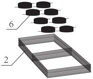
[0032] Such as Figure 1-Figure 4 As shown, the present invention discloses a wireless charging device, including a transmitting module and a plurality of corresponding receiving modules,

[0033] The transmitting module includes a power supply module for supplying power, a fission electric circuit connected to the power supply module, a transmitting antenna 2 connected to the fission circuit and converting electric energy into electromagnetic energy transmission, and used to control the The transmission control unit of the fission circuit, the signal demodulation circuit connected between the transmission antenna 2 and the transmission control unit, the transmission antenna 2 is rectangular;

[0034] Each of the receiving modules includes a receiving antenna 6 for receiving electromagnetic energy, a rectifying circuit connected to the receivi...


PUM


Abstract

The invention provides a wireless charging device and an electronic candle lamp with the same. The wireless charging device comprises a transmitting module and multiple receiving modules, wherein the transmitting module comprises a power supply module, a fission circuit, a transmitting antenna, a transmitting control unit and a signal demodulation circuit; the transmitting antenna is of a rectangular shape; each receiving module comprises a receiving antenna, a rectifying circuit, an energy storage module, a receiving control unit, an electric appliance connected with the receiving control unit and a signal modulation circuit; each receiving antenna is a cylindrical spiral coil; the projection of each receiving antenna is completely positioned in the rectangular area of the transmitting antenna, and an energy transfer method for multiple electromagnetic induction receiving devices by single electromagnetic induction transmitting device is realized; and moreover, the electromagnetic induction transmitting device has uniform electromagnetic field distribution and good charging stability.

Description

technical field [0001] The invention relates to a wireless charging device and an electronic candle lamp with the device. Background technique [0002] With the development of wireless charging technology today, as more and more companies join in, the competition has become more and more fierce, especially for industry standards. The current mainstream wireless charging standards mainly include: PowerMattersAlliance (PMA) standard, Qi Standard and Alliance for Wireless Power (A4WP) standard, etc., each standard has its own advantages and disadvantages, and also has its own supporters. [0003] Since the advent of electronic candles, their use safety, convenience, energy saving, and environmental protection are being liked by more and more people, especially in European and American countries, and gradually have a tendency to replace traditional life-fire stick candles. Electronic candles in the prior art are generally The charging interface is used for charging. This chargi...

Claims


Application Information

Patent Timeline
IPC IPC(8): H02J7/00H02J50/23H02J50/27F21S9/02F21V23/00F21Y115/10F21Y105/16
CPCH02J7/025F21S6/001F21S9/02F21V23/00F21V23/003
Inventor 王万里
Owner 江阴旺达电子有限公司
Learn More