Waveguide fed microwave coupled plasma generator

A technology for coupling plasma and generating devices, applied in the direction of plasma and electrical components, can solve problems such as deformation of PTFE supports, burning of microwave antennas, overheating of microwave antennas, etc., and achieve uniform distribution of the overall electromagnetic field and coupling of microwave energy High efficiency, stable and reliable effect

Active Publication Date: 2020-12-01
JILIN UNIV
View PDF13 Cites 0 Cited by
  • Summary
  • Abstract
  • Description
  • Claims
  • Application Information

AI Technical Summary

Problems solved by technology

[0003] 1) When the feed-in power is too large, due to the heating of the antenna, the polytetrafluoroethylene support member supporting the inner core of the coaxial connector is deformed, causing the position of the antenna to deviate from the normal size, which in turn causes further local overheating of the microwave antenna, and finally burns the microwave antenna;
[0004] 2) When the feed-in power is too large, sometimes partial discharge will occur near the antenna before the end face of the resonant cavity. This partial discharge is more likely to burn the microwave antenna and cause the resonant cavity to fail to work normally.
Partial holes on the side of the outer conductor will destroy the uniform distribution of the microwave electromagnetic field in the entire resonator, especially when holes are opened at the position where the electric field strength is the highest, which will lead to a decrease in the microwave energy coupling efficiency of the coaxial resonator

Method used


Image

  • Waveguide fed microwave coupled plasma generator
  • Waveguide fed microwave coupled plasma generator

Examples


Embodiment 1

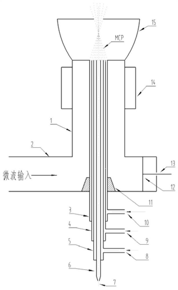
[0035] see figure 1 , a waveguide-feeding type MCP generating device, the generating device is mainly composed of a waveguide part and a coaxial resonant cavity part.

[0036] The waveguide part includes a standard waveguide 2 , a waveguide-coaxial conversion cone 11 , a short-circuit piston 12 and an adjustment rod 13 .

[0037] The first port of the standard waveguide 2 is connected to the microwave generation system, and the coaxial resonant cavity outer conductor 1 is vertically installed on the upper outer wall in the length direction between the first port and the second port of the standard waveguide 2, and the lower inner wall in the length direction of the standard waveguide 2 The waveguide-to-coaxial conversion cone 11 is installed, and the central axis of the cone coincides with the central axis of the outer conductor 1 . The second port corresponding to the first port of the standard waveguide 2 is closed by the short-circuit piston 12, and the short-circuit pisto...

Embodiment 2

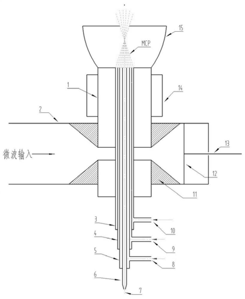
[0063] see figure 2 , the generating device is mainly composed of a waveguide part and a coaxial resonant cavity part.

[0064] The waveguide part includes a standard waveguide 2 , a waveguide-coaxial conversion cone 11 , a short-circuit piston 12 and an adjustment rod 13 . Wherein, the standard waveguide 2 , the short-circuit piston 12 and the adjusting rod 13 are completely the same as those in the first embodiment, and only the waveguide-coaxial conversion cone 11 is different from the first embodiment.

[0065] The waveguide-to-coaxial conversion cone 11 is two components with the same size, which are installed on the upper and lower sides of the inner wall of the standard waveguide 2 respectively, and the central axis of the cone coincides with the central axis of the outer conductor 1 . The cone can be a truncated cone, preferably, the angle of the cone is 40 degrees; it can also be a symmetrical trapezoid, preferably, the angle of the trapezoid is 40 degrees.

[0066...


PUM


Abstract

The waveguide-feeding type microwave coupling plasma generating device of the invention belongs to the technical field of microwave energy application. It consists of a waveguide part and a coaxial resonant cavity part; the waveguide part includes a standard waveguide (2), a waveguide-coaxial conversion cone (11), a short-circuit piston (12) and an adjustment rod (13); the coaxial resonant cavity part Including outer conductor (1), inner conductor (3), middle tube (4), inner tube (5), sample tube (6), sample inlet (7), inner layer gas inlet (8), middle layer gas inlet (9 ), outer gas inlet (10), cooling ring (14) and impedance matching cone (15). The device of the invention has no power input limitation of a radio frequency coaxial connector and a microwave antenna, and has the advantages of large feed-in power, long stable working time, high microwave energy coupling efficiency, and the like.

Description

technical field [0001] The invention belongs to the technical field of microwave energy application, and in particular relates to a waveguide-feeding type microwave coupled plasma generator, in particular a microwave coupled plasma (MCP for short) generator suitable for kilowatt-level or above power input. Background technique [0002] The microwave resonant cavity used in the microwave plasma torch (MPT) spectrometer to excite the light source is based on the inner core of the radio frequency coaxial connector connected to the microwave antenna, and microwave energy is fed into the resonant cavity through the microwave antenna. Related patents such as CN94205428.8. The resonant cavity adopts L16-KF RF coaxial connector, and the average power of long-term stable and reliable work is only below 200 watts. Another example is the patent CN106304602 A, which adopts the L29-KF type radio frequency coaxial connector to connect the microwave antenna, and the highest average power o...

Claims


Application Information

Patent Timeline
Patent Type & Authority Patents(China)
IPC IPC(8): H05H1/46
CPCH05H1/46H05H1/4622
Inventor 曹彦波曹博成
Owner JILIN UNIV
Why Eureka
Try Eureka