A flat panel array antenna for x-band

An array antenna and flat-panel technology, applied in the field of flat-panel array antennas, can solve the problems of low communication front port diameter efficiency, heavy flat-panel antenna weight, thick antenna array, etc., and achieve the effects of easy processing, strong applicability, and reduced processing difficulty

Active Publication Date: 2020-11-10
BEIJING RES INST OF TELEMETRY +1
View PDF8 Cites 0 Cited by
  • Summary
  • Abstract
  • Description
  • Claims
  • Application Information

AI Technical Summary

Problems solved by technology

Among them, the communication front-end in the form of a reflecting surface has low diameter efficiency, large volume, uncontrollable side lobes, and poor side lobes in the far area.
However, the various forms of panel antennas currently reported have low aperture efficiency (less than 65%) and relatively large volume. When circular polarization is required, the thickness of the antenna array will be thicker.
In addition, the weight of panel antennas in current applications has always been the biggest problem, which is difficult to overcome

Method used


Image

  • A flat panel array antenna for x-band
  • A flat panel array antenna for x-band
  • A flat panel array antenna for x-band

Examples


Embodiment Construction

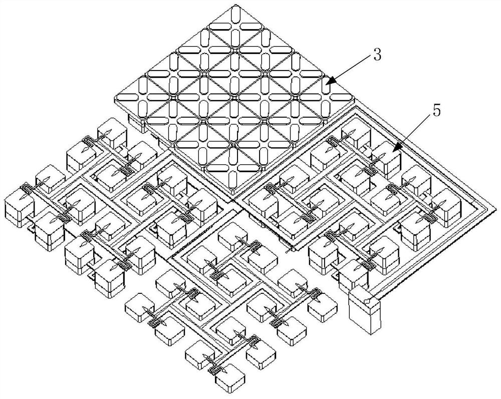
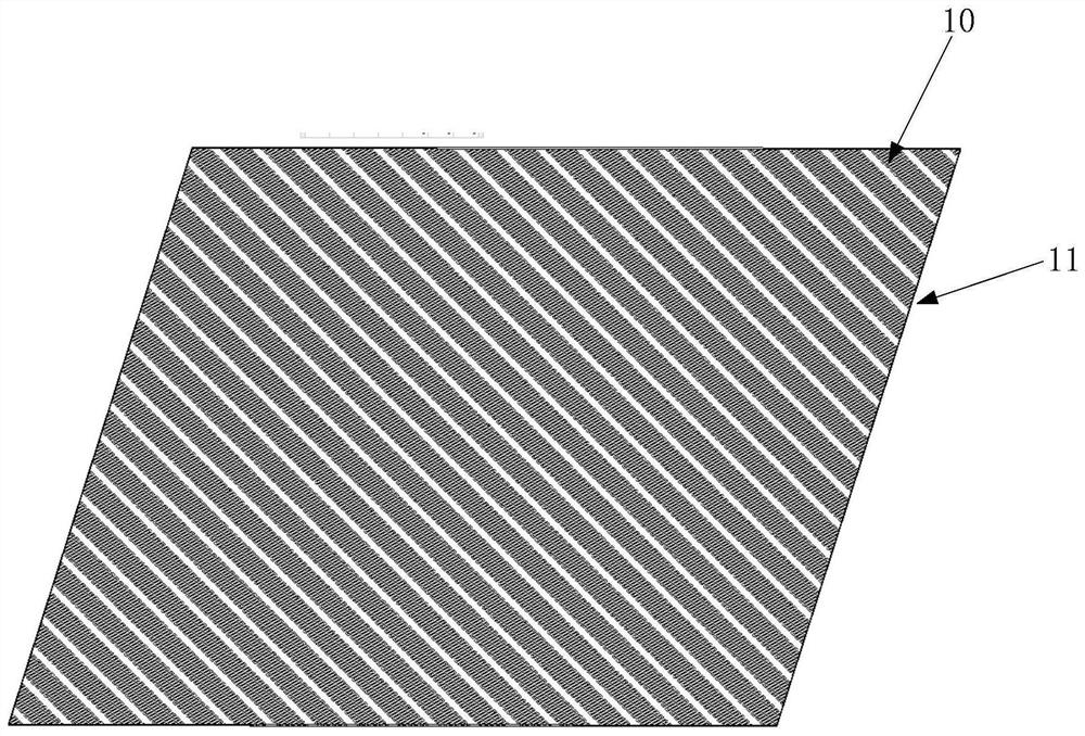
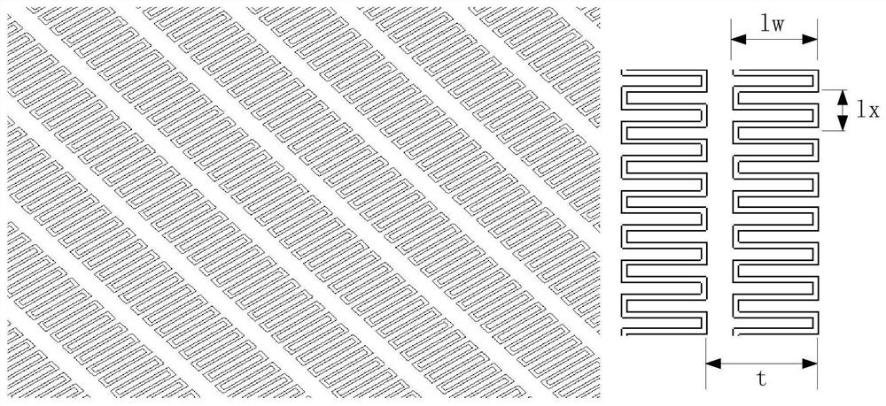
[0028] figure 1 The embodiment of the present invention provides a schematic diagram of the composition of the planar array antenna structure for the X-band; Figure 2 (a) is a schematic diagram of the structure of the circular polarization cover provided by the embodiment of the present invention; image 3 A schematic structural diagram of an antenna array unit provided for an embodiment of the present invention; Figure 3-1 Schematic diagram of the structure of the cross radiator slit provided for the embodiment of the present invention.

[0029] Such as figure 1 , Figure 2(a), image 3 with Figure 3-1 As shown, the panel array antenna for the X-band includes: several antenna array units, wherein the several antenna array units are arranged in m columns and n rows, wherein m is greater than 2, and n is greater than 2;

[0030] Each antenna array unit includes a circular polarization cover 1, a tuning air cavity 2, a cross radiator slot 3, a waveguide mode transmission ca...


PUM


Abstract

The invention discloses a flat plate array antenna for X frequency band, comprising a plurality of antenna array units. Each antenna array unit comprises a circularly-polarized cover, a tuning air cavity, a cross radiator slit, a waveguide mode type transmission cavity body, a square orthogonal mode coupler, a first strip line input terminal, and a second strip line input terminal. The tuning aircavity is disposed at the upper part of the cross radiator slit. Each slit of the cross radiator slit is arranged in a rotating manner at an interval of 90 D. The waveguide mode transmission cavity body is disposed at the lower part of the cross radiator slit. The square orthogonal mode coupler is disposed at the lower part of the waveguide mode transmission cavity body. The first strip line inputterminal is disposed at one side face of the square orthogonal mode coupler, and the second strip line input terminal is disposed at the other side face of the square orthogonal mode coupler, whereinthe two side faces are adjacent. The antenna array of the invention is advantageous in that efficiency is high, cross section is low, gain is high, wave beam is narrow, processing is easy.

Description

technical field [0001] The invention relates to a flat panel array antenna for X frequency band, which can be used as the front end of static communication and dynamic communication system at the ground end of the X frequency band satellite communication system, and belongs to the technical field of microwave antennas. Background technique [0002] At present, the application of X-band still has a good electromagnetic environment in the application field of satellite-to-earth communication, and it is not easy to be interfered by the ground system. And the confidentiality is good, the X-band communication system used by the Voyager system satellite in the United States can still work normally so far. The X-band flat-panel antenna invented in this patent specification is used in the field of small satellite measurement and control, which is booming in my country. With the help of the flat-panel antenna, it has the characteristics of high aperture efficiency. A single X-band fl...

Claims


Application Information

Patent Timeline
Patent Type & Authority Patents(China)
IPC IPC(8): H01Q1/36H01Q1/50H01Q15/24H01Q21/00H01Q21/06H01Q21/30H01Q23/00
CPCH01Q1/36H01Q1/50H01Q15/24H01Q21/0006H01Q21/061H01Q21/30H01Q23/00
Inventor 史永康李鹏飞
Owner BEIJING RES INST OF TELEMETRY
Why Eureka
Try Eureka