Cell panel mounting frame fixing mechanism used for photovoltaic tracking bracket

A fixing mechanism and battery panel technology, which is applied to the support structure of photovoltaic modules, photovoltaic power generation, photovoltaic modules, etc., can solve the problems of inconvenient installation of photovoltaic tracking bracket components, and achieve the solution of component falling off and damage, convenient installation, and convenient maintenance and replacement. Effect

Inactive Publication Date: 2017-02-22
江苏聚亿智能科技有限公司
View PDF11 Cites 3 Cited by
  • Summary
  • Abstract
  • Description
  • Claims
  • Application Information

AI Technical Summary

Problems solved by technology

[0007] Another object of the present invention is to provide a battery panel mounting frame fixing mechanism for photovoltaic tracking brackets, which is mainly composed of an upper pressing block, a lower pressing block, buckles and bolts. The battery assembly is placed between the blocks, and the upper pressing block, the lower pressing block, and the buckle are connected with the bolts. The cross-sectional shape of the bottom pressing block is an inverted trapezoidal structure, and there are two holes in the middle for tracking the bracket. The main beam is connected, the upper edge of the bottom pressure block is set in a barb shape, which is used to clamp the lower edge of the battery module, and the barb shape of the buckle is connected with the bottom beam to solve the technical problem of inconvenient installation of the photovoltaic tracking bracket assembly

Method used


Image

  • Cell panel mounting frame fixing mechanism used for photovoltaic tracking bracket
  • Cell panel mounting frame fixing mechanism used for photovoltaic tracking bracket
  • Cell panel mounting frame fixing mechanism used for photovoltaic tracking bracket

Examples


Embodiment Construction

[0032] The present invention will be further described in detail below in conjunction with the accompanying drawings, so that those skilled in the art can implement it with reference to the description.

[0033] It should be understood that terms such as "having", "comprising" and "including" as used herein do not entail the presence or addition of one or more other elements or combinations thereof.

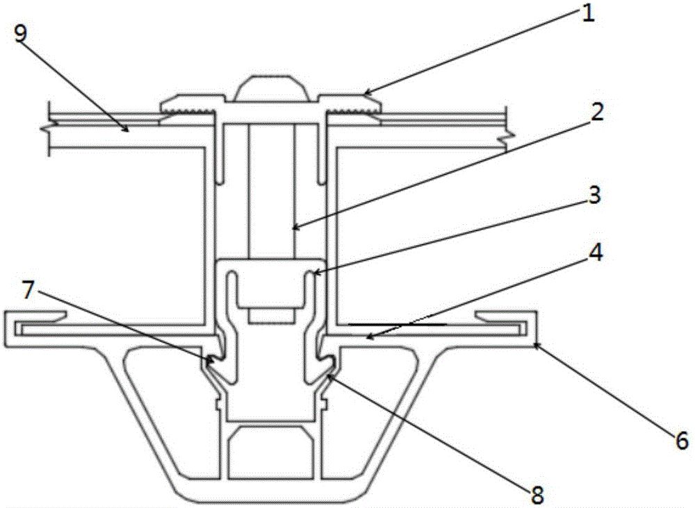
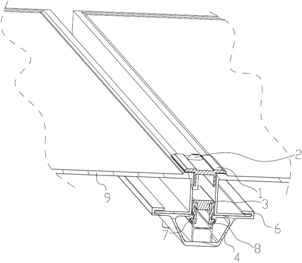
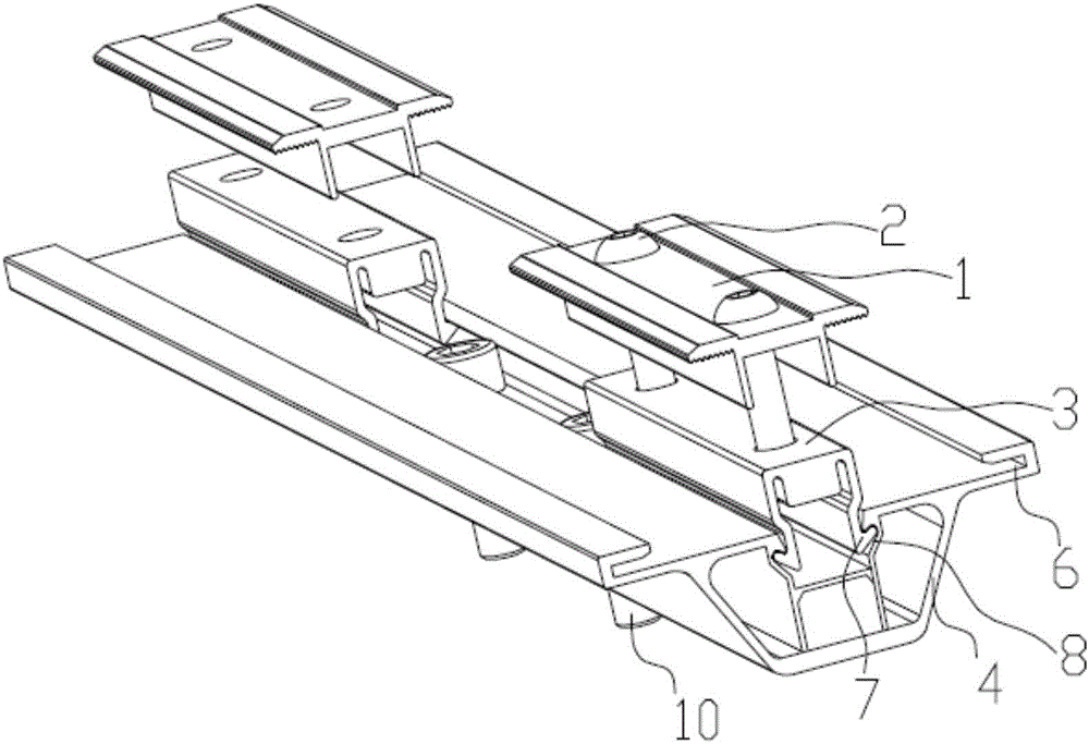
[0034] The present invention provides a battery panel mounting frame fixing mechanism for photovoltaic tracking brackets, such as Figure 1-7 As shown, it includes: the bottom pressure block 4 and the buckle 3 that are snap-connected, the upper pressure block 1 is fixed on the buckle 3, and the battery board mounting frame 9 is fixed between the upper pressure block 1 and the lower pressure block 4 , thereby fixing the battery panel mounting frame 9 .

[0035] The bottom pressing block 4 is a strip-shaped structure, and a rectangular channel 42 is provided in the middle along th...


PUM


Abstract

The invention discloses a cell panel mounting frame fixing mechanism used for a photovoltaic tracking bracket. The cell panel mounting frame fixing mechanism comprises: a bottom pressing block, a buckling part and an upper pressing block, wherein a rectangular slot channel is formed in the middle of the bottom pressing block; buckling seats, which are downward and reversely buckled, are symmetrically arranged on a side wall of the slot channel; platforms for supporting cell panel mounting frames are arranged at the upper end of the slot channel in a manner of extending toward two sides; reversed hooks are arranged at the edges of the outer sides of the platforms; a lower edge of one side of each cell panel mounting frame is limited in the corresponding reversed hook; buckling arms, adaptive to the slot channel, are arranged at the lower ends of two sides of the buckling part; buckle bodies, which are upward and reversely buckled, are arranged at the lower ends of the buckling arms; the buckle bodies are reversely buckled in the buckling seats; the upper pressing block is pressed into the upper ends of two adjacent cell panel mounting frames; the upper pressing block is locked with the buckling part through a bolt. The upper edge of the bottom pressing block is set into a reversed hook shape and is used for clamping the lower edge of a battery assembly; the buckling part is in the reversed hook shape and is connected with a bottom beam, so that the technical problem that a photovoltaic tracking bracket assembly is inconvenient to mount is solved.

Description

technical field [0001] The invention relates to the technical field of photovoltaic tracking systems, and more specifically, the invention relates to a fixing mechanism for a battery panel mounting frame used for a photovoltaic tracking bracket. Background technique [0002] With the worsening of global climate warming and the reduction of fossil fuels, finding a clean and renewable energy source has become an urgent issue for all mankind. As an inexhaustible, clean and pollution-free new energy source, solar energy has become an indispensable part of human energy use today, and solar power generation is the most widely used among them. [0003] In the application of solar power generation, due to the rotation of the earth, the orbit of the sun is from east to west, so the angle of the sun's illumination is changing every moment. In order to increase the amount of radiation received by the photovoltaic array, it is necessary to install solar panels The rack tracks the sunli...

Claims


Application Information

Patent Timeline
Patent Type & Authority Applications(China)
IPC IPC(8): H02S20/32
CPCH02S20/32Y02E10/50
Inventor 李华邵宗恒
Owner 江苏聚亿智能科技有限公司
Why Eureka
Try Eureka