
High-speed rotating cooling machine with structure for quickly disassembling and assembling target piece

A high-speed rotating and cooling machine technology, applied in cooling/ventilation/heating transformation, DC voltage accelerators, targets for generating nuclear reactions, etc., can solve the problems that plague designers, avoid radiation hazards, and improve efficiency Effect

Pending Publication Date: 2017-02-22
合肥华升泵阀股份有限公司
View PDF9 Cites 1 Cited by
  • Summary
  • Abstract
  • Description
  • Claims
  • Application Information

AI Technical Summary

Problems solved by technology

The high-speed rotary cooling machine has strong radiation in the workplace. How to maximize the disassembly and replacement efficiency of the target piece in order to minimize the stay time of the operator on site has been a major problem that has plagued the designers for a long time.

Method used


Image

  • High-speed rotating cooling machine with structure for quickly disassembling and assembling target piece
  • High-speed rotating cooling machine with structure for quickly disassembling and assembling target piece
  • High-speed rotating cooling machine with structure for quickly disassembling and assembling target piece

Examples


Embodiment Construction

[0030] For ease of understanding, here in conjunction with accompanying drawing, to the concrete implementation structure of the present invention, be further described as follows:

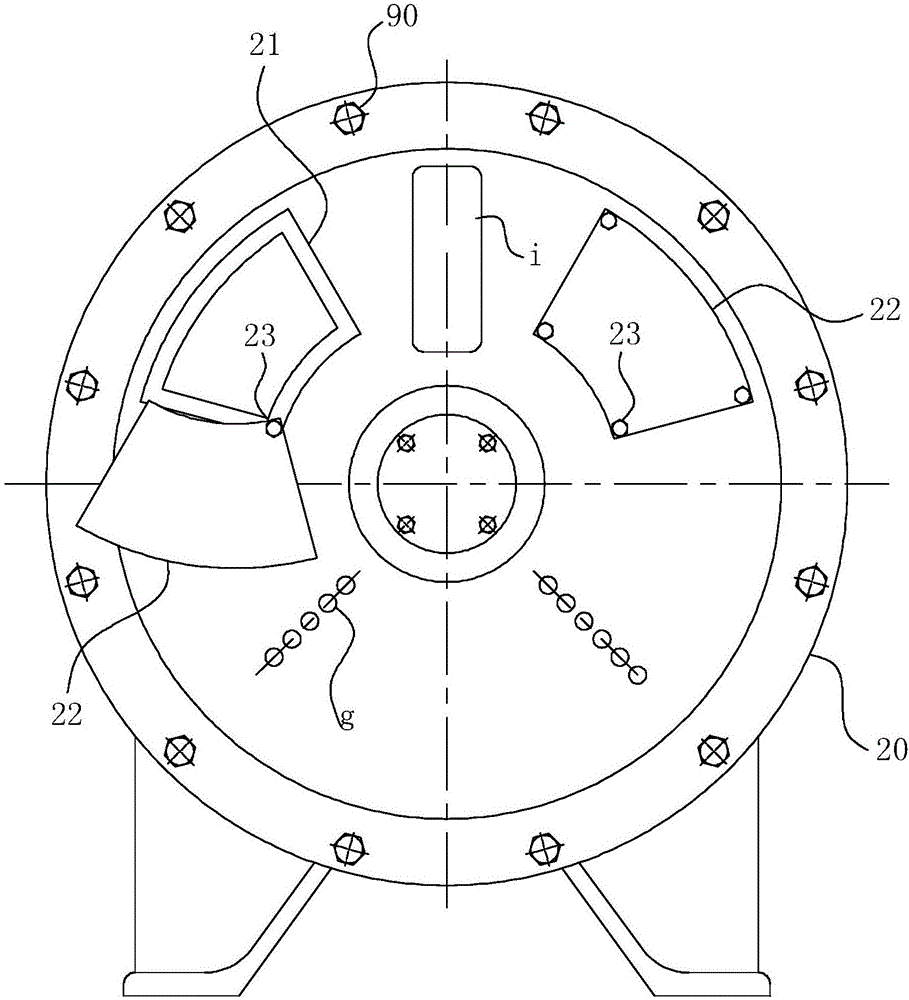
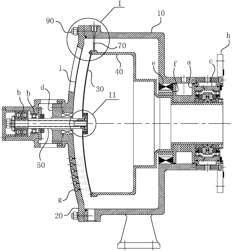
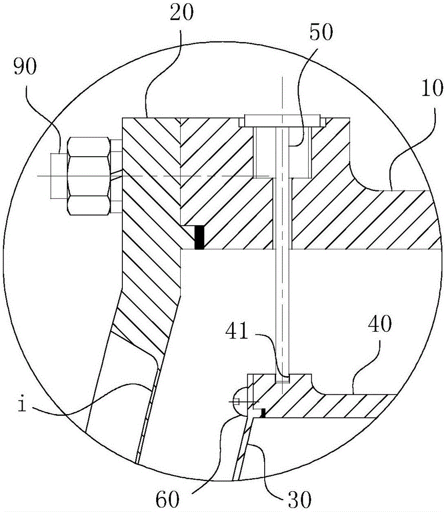
[0031] Concrete structure of the present invention, as Figure 1-4 As shown, its overall structure is a support structure at both ends, mainly composed of air bearing a, rolling bearing b, dry gas seal c, contact mechanical seal d, stator e, rotor f, rotating cavity (that is, sleeve-shaped bracket 40 ), the cooling machine shell (that is, the outer shell 10), the shell cover 20, the nozzle g, the target piece 30 and the connecting flange h and so on.

[0032] Among them, such as figure 1 As shown, the power unit of the device is mainly composed of a stator e and a rotor f. The rotor f is directly hooped on the sleeve-shaped bracket 40, which ensures the reliability and compactness of the driving structure. The radial support of this device is provided by the figure 2 The air bearing a on the ...


PUM


Abstract

The invention belongs to the field of high-speed rotating cooling machines, and specifically relates to a high-speed rotating cooling machine with a structure for quickly disassembling and assembling a target piece. The cooling machine comprises a housing and a housing cover. A sleeve-shaped bracket is coaxially disposed in a cylindrical cavity of the external housing, and forms rotating fit with the cylindrical bottom of the housing. The cooling machine also comprises a rotating shaft, and an end of the rotating shaft extends towards the target surface of the target piece along the axis of the target piece, and forms detachable fixed connection fit with the target surface of the target piece. The cylindrical mouth of the sleeve-shaped bracket is uniformly provided with threaded holes, and the target surface of the target piece is provided with installation holes. Fastening screws pass through the installation holes to form screw-thread fit with the threaded holes. The housing cover is provided with an operation window, and a hole region of the operation window is located on the installation path of at least one fastening screen. A hole end, located on the outer wall of the housing cover, of the operation window is provide with a sealing cover. The cooling machine can effectively improve the disassembly and assembly and replacement efficiency of the target piece, and can reduce the radiation damage, caused by a high-speed rotating cooling machine workplace, to an operator to the greatest degree.

Description

technical field [0001] The invention belongs to the field of high-speed rotary cooling machines, and in particular relates to a high-speed rotary cooling machine with a structure for quickly disassembling and assembling targets. Background technique [0002] The high-speed rotary cooler is used in the neutron generator and is the key equipment of the neutron generator. Its performance directly determines the neutron strength and stability of the neutron generator. When the deuterium ion beam is accelerated and transmitted to the tritium target in the high-speed rotary cooler, and undergoes a deuterium-tritium fusion reaction with the tritium nucleus in the target to generate neutrons, the neutrons produced can be used for neutron cancer treatment, etc. in a specific industry. Since the tritium atoms on the target sheet of the high-speed rotary cooler will gradually fail due to fusion reaction, the target sheet must be replaced after the high-speed rotary cooler has been in ...

Claims


Application Information

Patent Timeline
IPC IPC(8): H05H6/00H05K7/20
CPCH05H6/00H05K7/20218
Inventor 柴立平张军辉何玉杰熊广磊李强尹来弟葛帝宏蔡明虎
Owner 合肥华升泵阀股份有限公司
Learn More