Method for laminating film on whole screen
A film and attachment technology, applied in the electronic field, can solve the problems of film falling off, poor visual effect, and small coverage of the film, and achieve the effect of improving the visual effect and not easy to peel off and fall off.
- Summary
- Abstract
- Description
- Claims
- Application Information
AI Technical Summary
Problems solved by technology
Method used
Image

Examples
Embodiment 1
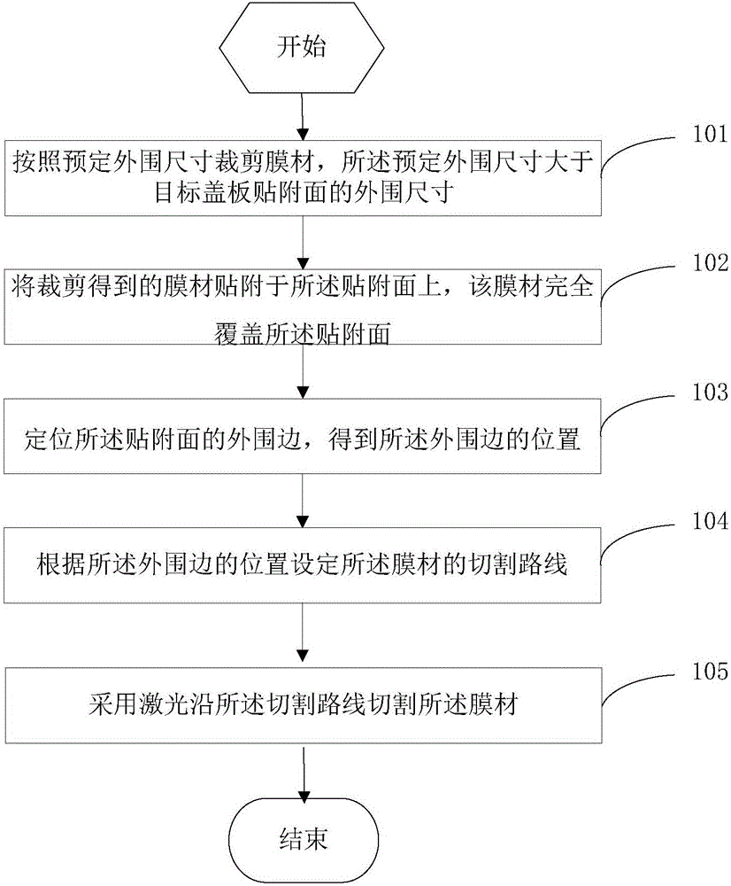
[0037] This embodiment provides a method for full-screen attachment of film materials, such as figure 1 shown, including:
[0038] Step S101: Cutting the film material according to a predetermined peripheral size, the predetermined peripheral size being larger than the peripheral size of the attaching surface of the target cover plate.
[0039] In this step, the film material is cut according to a predetermined peripheral size, and the predetermined peripheral size is larger than the peripheral size of the attaching surface of the target cover plate. Specifically, the predetermined peripheral dimension is set to be 0.5 mm to 5 cm larger than the peripheral dimension of the target cover attachment surface, including the endpoint value, that is, the area of the figure formed by the predetermined peripheral size is larger than the target cover attachment surface, and the predetermined The distance between the peripheral edge of the figure formed by the peripheral dimension and...
Embodiment 2
[0074] This embodiment provides a method for attaching a full-screen film material. Unlike the previous embodiment, step 104 in this embodiment includes:
[0075] According to the position of the peripheral edge, a computer-aided design CAD system is used to determine the cutting route of the membrane material.
[0076] Specifically, according to the position information of the peripheral edge obtained by the CCD positioning system, a computer-aided design CAD system is used to set the cutting route of the film material. In this step, the shape information of the attachment surface is input in the CAD in advance, and the cutting route is set to be along the periphery of the attachment surface according to the position information of the peripheral edge obtained by the CCD positioning system. The edge is cut, and in this embodiment, the cutting route is cut clockwise along the peripheral edge. In other embodiments of the present invention, the cutting route may also be set to ...
Embodiment 3
[0079] Different from the above-mentioned embodiments, in this embodiment, the laser-cut film material is an anti-glare film.
[0080] Using carbon dioxide CO with a maximum power of 60W and a maximum speed of 600mm / s 2 laser.
[0081] The thickness of the anti-glare film is 0.17mm, the corresponding laser power is 7W-8.5W inclusive, and the speed is 230mm / s-250mm / s inclusive. Specifically, the laser power may be 7.8W, and the speed may be 180mm / s.
[0082] Wherein, the structure of the anti-glare film is: a TAC (Tri-AcetylCellulose, triacetylcellulose) film coated with an anti-glare coating.
[0083] By adopting the above parameters for laser cutting, the membrane material beyond the peripheral edge of the attachment surface can be completely cut off without damaging the attachment surface.
[0084] Attach the film material by the method in this embodiment, cut the film material into a film material whose peripheral size is larger than the peripheral size of the attachment...
PUM
| Property | Measurement | Unit |
|---|---|---|
| Thickness | aaaaa | aaaaa |
| Thickness | aaaaa | aaaaa |
| Thickness | aaaaa | aaaaa |
Abstract
Description
Claims
Application Information
 - Generate Ideas
- Intellectual Property
- Life Sciences
- Materials
- Tech Scout
- Unparalleled Data Quality
- Higher Quality Content
- 60% Fewer Hallucinations
Browse by: Latest US Patents, China's latest patents, Technical Efficacy Thesaurus, Application Domain, Technology Topic, Popular Technical Reports.
© 2025 PatSnap. All rights reserved.Legal|Privacy policy|Modern Slavery Act Transparency Statement|Sitemap|About US| Contact US: help@patsnap.com