
Clutch disk comprising a centrifugal pendulum

A technology of clutch disc and centrifugal force pendulum, which is applied in clutches, friction clutches, mechanically driven clutches, etc., and can solve problems such as residual vibration

Active Publication Date: 2017-02-22
SCHAEFFLER TECH AG & CO KG
View PDF8 Cites 5 Cited by
  • Summary
  • Abstract
  • Description
  • Claims
  • Application Information

AI Technical Summary

Problems solved by technology

However, in the case of the corresponding cylinder assemblies, partial vibrations remain in the event of possible partial shutdown of cylinders and similar components of internal combustion engines

Method used


Image

  • Clutch disk comprising a centrifugal pendulum
  • Clutch disk comprising a centrifugal pendulum
  • Clutch disk comprising a centrifugal pendulum

Examples


Embodiment Construction

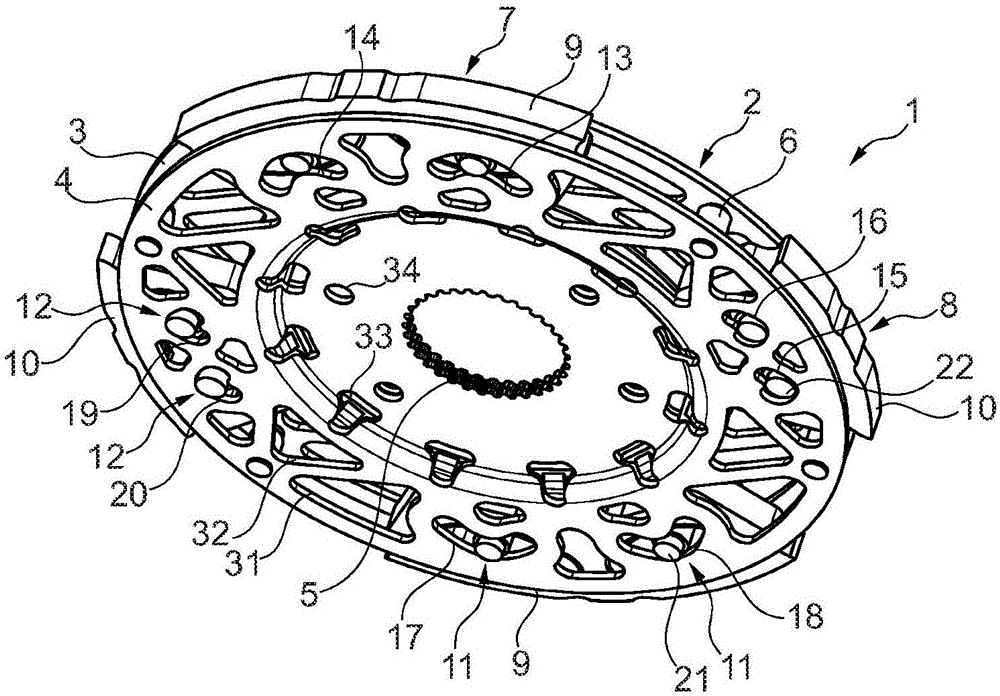
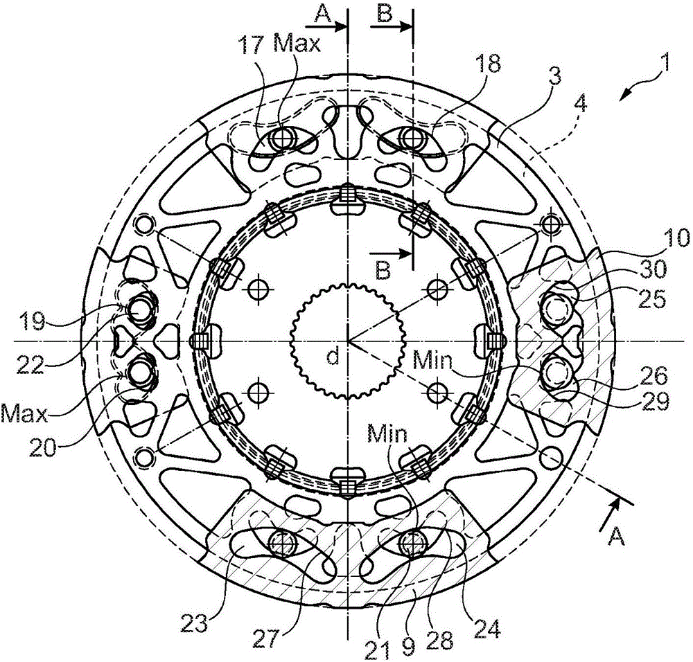
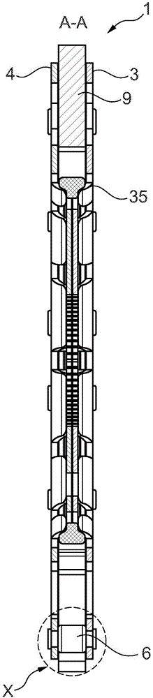
[0020] figure 1 The centrifugal pendulum 1 is shown in a perspective view and is held in a rotationally fixed manner on the hub of a clutch disk (not shown). The rest of the design of the clutch disk is known and can be obtained, for example, from the cited prior art. Centrifugal pendulum 1 comprises a support 2 formed from two disk parts 3 , 4 which are preferably designed as identical parts. The centrifugal pendulum 1 is held on the hub in a rotationally fixed manner by means of the inner toothing 5 of the disk parts 3 , 4 and is fixed in the axial direction, for example by caulking. The disk parts bear against each other radially on the inside and widen in the axial direction on the radial outside and are connected to one another at a distance in the axial direction by means of spacer pins 6 . In the axial direction, two pendulum groups 7 , 8 are accommodated between the two disk parts 3 , 4 . The pendulums 9 , 10 of the two pendulum groups 7 , 8 are each arranged diame...


PUM


Abstract

The invention relates to a clutch disk comprising an input piece which is arranged to be rotatable about an axis of rotation (d) and supports friction linings radially on the outside, and an output piece which is in the form of a hub connected to a transmission input shaft for conjoint rotation therewith, and, optionally, a torsional vibration damper which is arranged radially within the friction linings so as to be effective between the input piece and the output piece in the circumferential direction, and a centrifugal pendulum (1) which comprises a support (2) connected to the hub for conjoint rotation therewith and pendulums (9, 10) that are distributed along the circumference of the support (2) and are suspended thereon so as to oscillate within a centrifugal field of the rotating clutch disk. In order to be able to design the centrifugal pendulum (1) in such a way that same does not create any dynamic loads on the transmission input shaft on at least two orders of oscillation, at least two groups (7, 8) of pendulums are provided, and said at least two groups (7, 8) are alternatingly distributed along the circumference, are adjusted to different orders of oscillation, and each comprise pendulums (9, 10) that are arranged in such a way as to be rotationally symmetrical to the axis of rotation (d).

Description

technical field [0001] The invention relates to a clutch disc having an input part, an output part and optionally a torsional vibration damper as well as a centrifugal force pendulum, the input part carrying friction linings radially on the outside and being rotatable about an axis of rotation Arranged in a manner, the output member is configured as a hub connected in a rotationally locked manner with the transmission input shaft, the torsional vibration damper acts in the circumferential direction between the input member and the output member and is arranged radially on Inside the friction lining, the centrifugal pendulum has a carrier, which is connected in a rotationally fixed manner to the hub, and a pendulum, which is distributed circumferentially on the carrier and oscillates in the centrifugal force field of the rotating clutch disc Ground suspension. Background technique [0002] WO 2012 / 079557 A1 discloses a clutch disc with centrifugal pendulums, in which three p...

Claims


Application Information

Patent Timeline
Patent Type & Authority Applications(China)
IPC IPC(8): F16F15/14F16D13/64
CPCF16D13/64F16F15/145F16D13/644F16D2300/22
Inventor A·鲁施
Owner SCHAEFFLER TECH AG & CO KG
Learn More