Supercharge Your Innovation With Domain-Expert AI Agents!

High conductance valve for fluids and vapors

A fluid and fluid volume technology, used in lift valves, multi-way valves, valve devices, etc., to solve problems such as internal pollution sources on the surface area

Active Publication Date: 2017-02-22
HORIBA STEC CO LTD
View PDF17 Cites 0 Cited by
  • Summary
  • Abstract
  • Description
  • Claims
  • Application Information

AI Technical Summary

Problems solved by technology

Subsequent experience has shown that the relatively large surface area associated with corrugation of the bellows can be problematic as an internal source of contamination in high-purity fluid delivery systems

Method used


Image

  • High conductance valve for fluids and vapors
  • High conductance valve for fluids and vapors
  • High conductance valve for fluids and vapors

Examples


Embodiment Construction

[0072] The invention is not limited in its application to the details of construction and arrangement of parts set forth in the following description and illustrated in the drawings. The invention is applicable to other embodiments and of being practiced or carried out in various ways. Also, the phraseology and terminology employed herein are for the purpose of description and should not be regarded as limiting. As used herein, "comprises," "including," or "having," "comprising," "involving," and variations thereof are intended to cover the items listed thereafter and equivalents thereof as well as additional items. The directional adjectives "inner", "outer", "upper", "lower" and similar terms are intended to aid in the understanding of relative relationships among design elements and should not be construed as indicating absolute directions in space or viewed as limiting of.

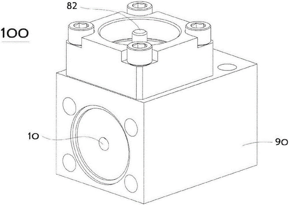
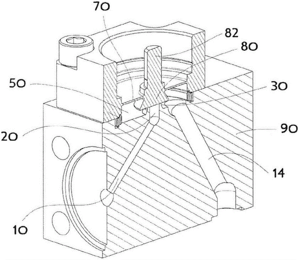
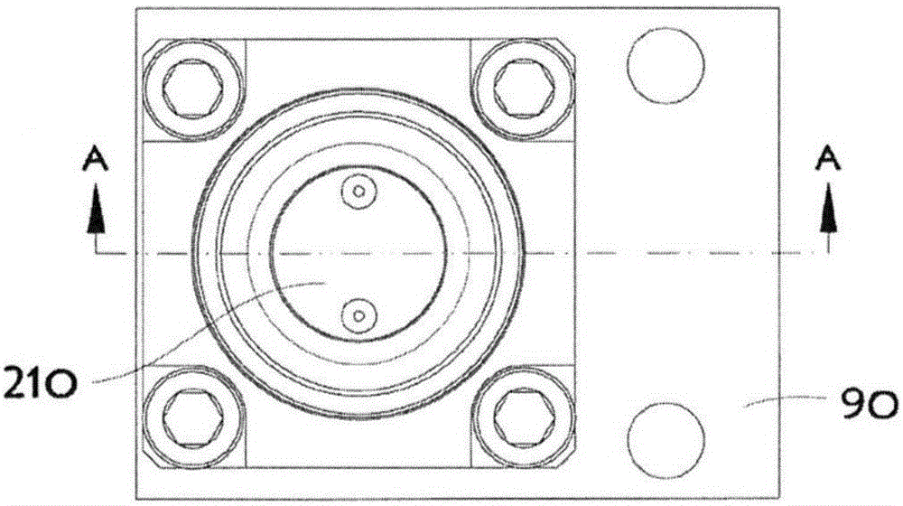
[0073] figure 1 and Figure 1A A representative example of a typical commonly used design valve...


PUM


Abstract

A high conductance valve for use in fluid delivery systems is comprised of a flat non-circular orifice ridge adjacent to which a control plate having a planar control surface is proximally positioned to adjust the valve effective opening area and thereby the conductance of the valve. The length of the non-circular orifice ridge periphery is substantially greater than the circumference of a similarly sized circular orifice and therefore the realized effective opening area is also substantially greater despite having a similar footprint.

Description

Background technique [0001] The present invention relates to the old and well known field of valves. A very simple valve can consist of an inlet channel, an outlet channel and a movable or deformable control element arranged between these two channels. The delivery of fluid from one channel to the other is regulated by movement and / or deformation of the control element. The direction of fluid delivery may be unrelated to well-known nominal designs (e.g., inlet and outlet), or these designs may be based on application-related reasons (e.g., in the case of non-return valves used to restrict flow to only a preferred direction) to make a selection. Many valves have inlet and outlet passages formed as fluid conduits within parts of the valve body and control elements that are moved by an actuator (or the fluid itself) to a movable position within the chamber of the valve. change position. The controlled fluid can be a liquid, gas, vacuum, vapor, or a combination of substances i...

Claims


Application Information

Patent Timeline
IPC IPC(8): F16K1/32F16K27/02
CPCF16K1/12F16K1/42F16K31/0655Y10T137/0318Y10T137/86493F16K1/36F16K11/04F16K27/02
Inventor 基姆·恩格西·乌
Owner HORIBA STEC CO LTD
Features
  • R&D
  • Intellectual Property
  • Life Sciences
  • Materials
  • Tech Scout
  • Unparalleled Data Quality
  • Higher Quality Content
  • 60% Fewer Hallucinations
Learn More