
Screen drawing software

A technology of drawing software and engineering data, which is applied in the field of drawing software, can solve the problems of increasing setting items and complicated setting order, and achieve the effect of easy creation and improved technical level

Active Publication Date: 2017-02-22
MITSUBISHI ELECTRIC CORP
View PDF6 Cites 2 Cited by
  • Summary
  • Abstract
  • Description
  • Claims
  • Application Information

AI Technical Summary

Problems solved by technology

In addition, due to the advancement of functions, the number of setting items on the sub-function setting screen increases, and the setting procedure becomes complicated.

Method used


Image

  • Screen drawing software
  • Screen drawing software
  • Screen drawing software

Examples


Embodiment approach 1

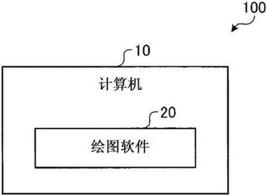
[0026] figure 1 It is a figure which shows the structure of Embodiment 1 of the project data creating apparatus which concerns on this invention. The engineering data creation device 100 is configured by the computer 10 executing the drawing software 20 . In other words, the computer 10 that is executing the drawing software 20 becomes the engineering data creating device 100 .

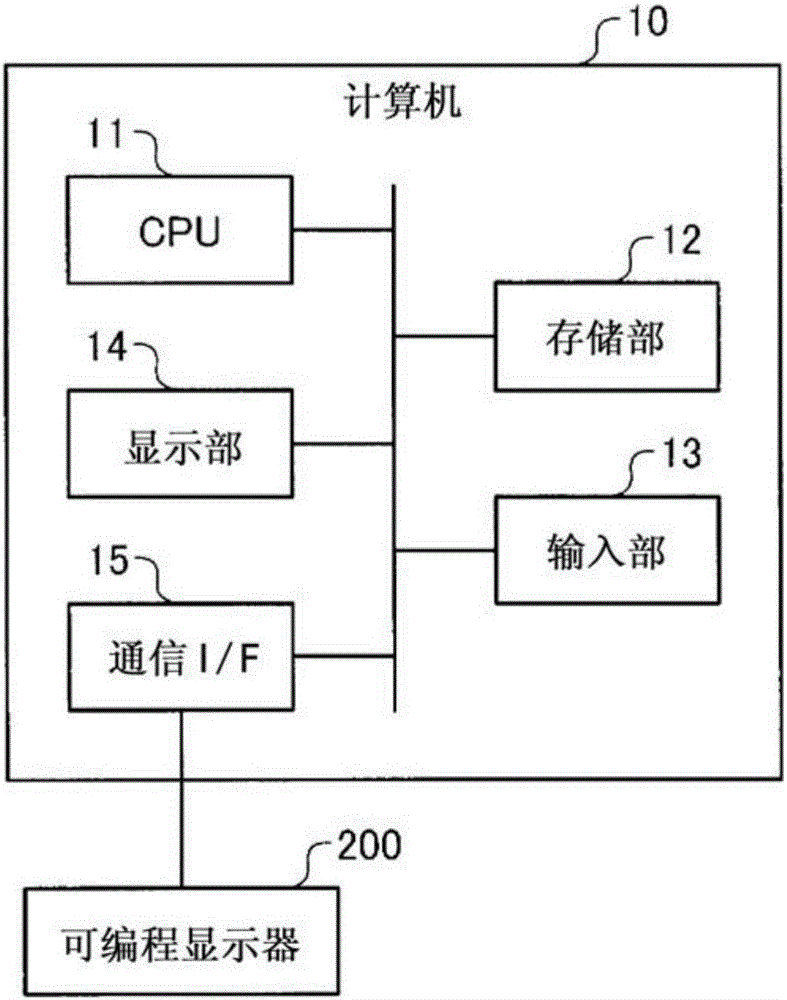
[0027] figure 2 It is a figure which shows the structure of the computer used for a project data creation apparatus. The computer 10 has a CPU 11 , a storage unit 12 , an input unit 13 , a display unit 14 , and a communication I / F (InterFace) 15 . The CPU 11 configures a plurality of functional units on the computer 10 by executing the drawing software 20 . The input unit 13 is an input device such as a keyboard or a mouse. The display unit 14 is a display device such as a liquid crystal display device. Communication I / F 15 is an interface for communicating with programmable display 200 .

[0...

Embodiment approach 2

[0047] The configuration of the project data creating device according to the second embodiment is substantially the same as that of the first embodiment, but the layout of the setting screen of the sub-function accompanying the data flow is such that the setting dialog call buttons are displayed along the data flow. In addition, the sub-functions associated with data flow refer to sub-functions that perform data transmission and reception with external devices such as PLCs.

[0048] In the following description, a logging function is used as an example of a sub-function accompanying data flow. The logging function is a function to collect and store the device values ​​of the connected device in the buffer area or data memory at any timing or at any cycle. Therefore, in the case of executing the logging function, there is a data flow of the device of the connected device → the buffer area of ​​the programmable display → the data memory. As the setting of the logging function,...


PUM


Abstract

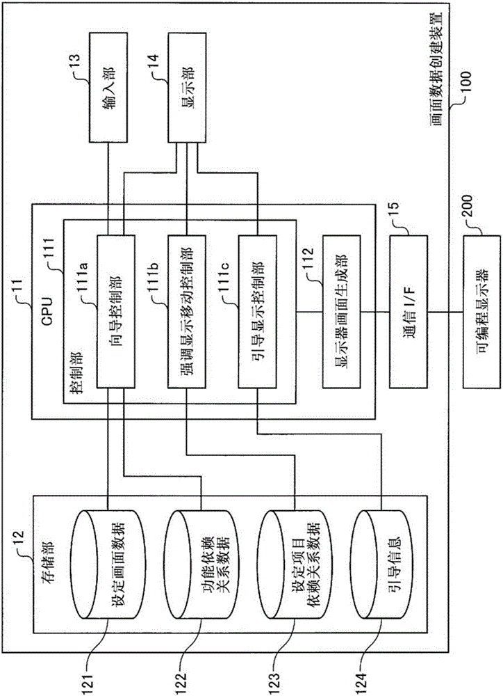
The invention discloses a screen drawing software. In the present invention, a computer is caused to function as a wizard controller (111a) and a highlight movement controller (111b). The wizard controller (111a) stores function-dependency-relation data (122) representing a sequence for setting up a plurality of sub functions included in the function of a programmable display (200) into a storage (12); stores setting-item dependency-relation data (123) representing a sequence for setting up each setting item on a sub-function setting screen into the storage (12); displays a list of a plurality of sub functions on a display (14) each sub function bearing a sequential number based on the function-dependency-relation data (122); and displays the setting screen for a sub function selected from the displayed list of sub functions on the display (14). The highlight movement controller (111b) highlights each setting item on the sub function setting screen sequentially on the basis of the setting-item dependency-relation data (123).

Description

technical field [0001] The invention relates to a drawing software. Background technique [0002] The programmable display is usually connected with external devices such as a programmable logic controller (Programmable Logic Controller, PLC), and is used for collecting and displaying various data of these external devices, and controlling the external devices. [0003] For this reason, generally, a project data creation device, which is a design tool for programmable displays, is used to set various functions such as alarm functions, data display and input functions, graph display functions, and recipe functions to create project data, so that programmable The display collects data from the external device, displays the status of the external device, and controls the external device. Also, the engineering data creation device is formed by causing a computer to execute drawing software. [0004] In recent years, along with the increase in functionality of programmable disp...

Claims


Application Information

Patent Timeline
IPC IPC(8): G09G5/00G05B19/05G06F3/048G09G5/10G06F3/0484
CPCG05B19/054G05B2219/13144G05B2219/35489G06F9/453G05B19/05G05B2219/13004G05B2219/13049G06F3/0484
Inventor 岩城朝厚东里夏
Owner MITSUBISHI ELECTRIC CORP
Learn More