Multiple-wire winding method, multiple-wire winding device, and wound coil component

A winding method and winding device technology, applied in coil manufacturing, electrical components, fixed transformers or mutual inductance, etc., can solve problems such as wire injury and wire disconnection, and achieve the effects of preventing injury, not easy to loosen, and reducing the risk of occurrence

Active Publication Date: 2017-02-22
MURATA MFG CO LTD
View PDF8 Cites 6 Cited by
  • Summary
  • Abstract
  • Description
  • Claims
  • Application Information

AI Technical Summary

Problems solved by technology

On the other hand, in the case where the start ends and end portions of all the electric wires 301 to 303 are fixed to the electrodes 304 to 309 along the axis of the core as in (b), the risk of occurrence of a short circuit as described above can be

Method used


Image

  • Multiple-wire winding method, multiple-wire winding device, and wound coil component
  • Multiple-wire winding method, multiple-wire winding device, and wound coil component
  • Multiple-wire winding method, multiple-wire winding device, and wound coil component

Examples


no. 1 example -

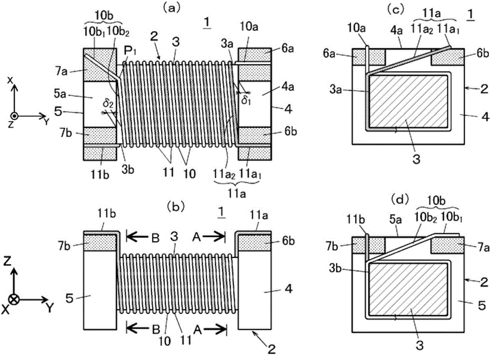
[0049] figure 1 It is an example of the coil component 1 manufactured by the winding method concerning this invention, and the example of a 2-wire common mode choke coil is shown here. The present coil component 1 includes a core body 2 made of a magnetic material. The core body 2 has a winding core portion 3 at its central portion, and a pair of flange portions 4, 5 at both ends in the axial direction. The winding core portion 3 has a rectangular parallelepiped shape having an upper and lower surface and two side surfaces, and two electric wires 10 and 11 are wound in parallel on the peripheral surface of the winding core portion 3 . Among them, in figure 1 Here, the axial direction of the core body 2 is defined as the Y axis, the horizontal direction perpendicular to the Y axis is defined as the X axis, and the vertical direction is defined as the Z axis.

[0050] On the mounting surface side of the flange parts 4, 5 (in figure 1 (indicated as the upper side, but it i...


PUM


Abstract

To provide a multiple-wire winding method, a multiple-wire winding device, and a wound coil component that make it possible to reduce both damage done to wires and the risk of short-circuits between said wires and electrodes at different potentials. In this winding method, starting sections of a plurality of wires are first guided from the outside of a flange on one end to the inside thereof and then laid out on top of and affixed to electrodes on said flange. The wires are guided laterally with respect to the axis of a core and are wound around a winding-core section together. Next, a wire-bending implement is made to contact a flat surface of a flange on the other end between a plurality of electrodes, ending sections of the wires are guided from the inside of said flange to the outside thereof, and the ending section of at least one wire is hooked between the wire-bending implement and the flange on the other end and bent with said wire(s) under tension. The ending sections of the plurality of wires are then affixed to the corresponding electrodes on the flange on the other end. By bending the wire ending section(s) laterally, the risk of short-circuits with electrodes at different potentials is reduced.

Description

technical field [0001] The present invention relates to a multi-wire winding method, a multi-wire winding device, and a wire-wound coil component for forming a coil component by winding a plurality of electric wires around a winding core portion of a core body. In particular, it relates to a core having flanges on one end side and the other end in the axial direction, and having a flat surface on the mounting surface side of each flange, and forming multiple holes connected to electric wires at intervals on the flat surfaces. A coil part of an electrode, a winding method of the coil part, and a winding device. Coil components targeted by the present invention include, for example, common mode choke coils such as 2-wire, 3-wire, and 4-wire, pulse transformer coils, and the like. Background technique [0002] In the past, it was known that a Figure 21 A coil component 100 having a structure as shown (here, a 2-wire common mode choke coil is shown). Reference numeral 101 is ...

Claims


Application Information

Patent Timeline
IPC IPC(8): H01F41/069H01F19/00H01F19/06H01F41/04
CPCH01F19/00H01F19/06H01F41/04H01F41/06
Inventor 山北高之堀内康次平井真哉桥本良太
Owner MURATA MFG CO LTD
Why Eureka
Try Eureka