
Automatic cutting and winding device and working method thereof

A coiling device and automatic cutting technology, applied in the direction of coiling strips, transportation and packaging, thin material processing, etc., can solve the problems of continuous coiling, strip falling off, low efficiency, etc., to avoid folding and deformation, avoid Falling off, high efficiency

Active Publication Date: 2017-03-01
CHANGZHOU HENGLIDE PACKAGING MACHINERY CO LTD
View PDF8 Cites 0 Cited by
  • Summary
  • Abstract
  • Description
  • Claims
  • Application Information

AI Technical Summary

Problems solved by technology

[0002] Coiling, changing, and cutting are the last steps of the coated strip production line. At present, most of the winding methods are to wind the strip directly on the winding shaft after it comes out. As the length of the strip increases, its diameter increases. When the coiling is close to the set length or diameter, the coiling shaft is turned over to the cutting station and switched to another coiling shaft. During the coiling shaft flipping process, the coiled strip is folded and deformed into waste products. The coiling speed The higher it is, the more folded and deformed strips will be involved, and the waste will be more serious. At the same time, the strips will fall off during the cutting process, which cannot be coiled continuously, and the efficiency is low.

Method used


Image

  • Automatic cutting and winding device and working method thereof
  • Automatic cutting and winding device and working method thereof
  • Automatic cutting and winding device and working method thereof

Examples


Embodiment 1

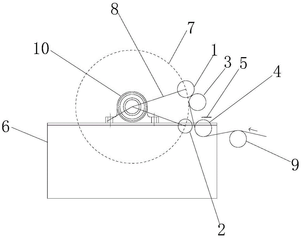
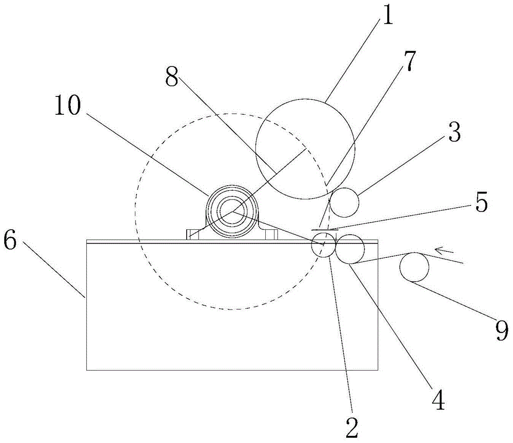
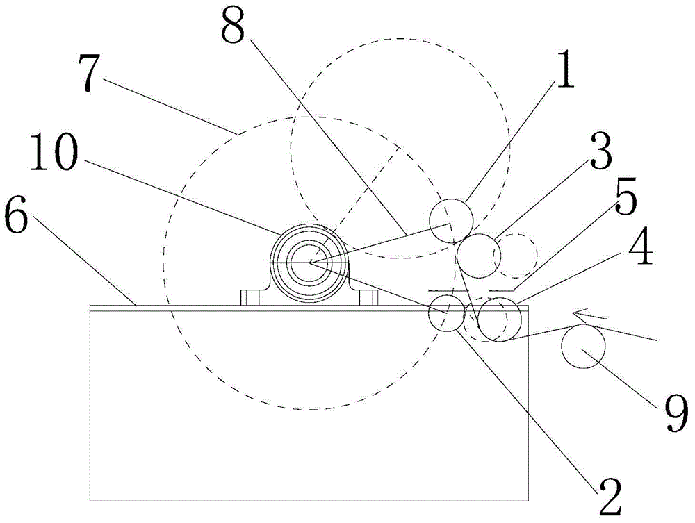
[0027] Example 1 as Figure 1-3 , the automatic cutting coiling device of the present embodiment includes a first coiling shaft 1, a second coiling shaft 2, a first pressing roller 3, a second pressing roller 4, a cutter 5 and a workbench 6.

[0028] The first take-up shaft 1 and the second take-up shaft 2 with the same structure are rotated by the take-up motor and revolve around the same circle 7 .

[0029] Each of the two ends of the first coiling shaft 1 and the second coiling shaft 2 is movably connected with a connecting rod 8, and the bottom end of each connecting rod 8 is fixed on the rotating bracket 10 on the workbench 6, and the rotating bracket 10 is provided with a drive The first winding shaft 1 and the second winding shaft 2 are rotated along the circumference 7 by the turning motor, which is convenient for turning over the positions of the first winding shaft and the second winding shaft. Limit switches for controlling the revolution positions of the first win...


PUM


Abstract

The invention relates to an automatic cutting and winding device and a working method thereof. The automatic cutting and winding device comprises a first winding shaft, a second winding shaft, a first pressure roller, a second pressure roller and a cutter. The first and second winding shafts of the same structure achieve autoroatation through a driving mechanism, the linear speed of autoroatation is matched with the conveying speed of a belt material, and the first and second winding shafts are suitable for revolving around the same circumference. The belt material is wound by the first winding shaft under cooperation of the first pressure roller, the second winding shaft is static, and the second pressure roller guides the belt material. When the amount of the belt material wound on the first winding shaft reaches the preset value, the second winding shaft starts autoroatation, the second pressure roller quickly displaces to the position attached to the second winding shaft, the cutter cuts off the belt material quickly, and the subsequent belt material is attached to the second winding shaft and starts to be wound by the second winding shaft. Through alternate cooperation of the first winding shaft and the second winding shaft, continuous winding and automatic cutting can be achieved, and the situation the wound belt material is folded and deformed and becomes waste is avoided.

Description

technical field [0001] The invention relates to a coating machine winding matching device and its working method, in particular to a coating machine automatic cutting and continuous winding device and its working method. Background technique [0002] Coiling, changing, and cutting are the last steps of the coated strip production line. At present, most of the winding methods are to wind the strip directly on the winding shaft after it comes out. As the length of the strip increases, its diameter increases. When the coiling is close to the set length or diameter, the coiling shaft is turned over to the cutting station and switched to another coiling shaft. During the coiling shaft flipping process, the coiled strip is folded and deformed into waste products. The coiling speed The higher it is, the more folded and deformed strips will be involved, and the waste will be more serious. At the same time, the strips will fall off during the cutting process, which cannot be coiled c...

Claims


Application Information

Patent Timeline
Patent Type & Authority Applications(China)
IPC IPC(8): B65H19/22B65H19/26
CPCB65H19/22B65H19/26B65H2301/418
Inventor 刘小华顾良武许威时旭萍
Owner CHANGZHOU HENGLIDE PACKAGING MACHINERY CO LTD
Learn More