Equipment connection method and device
A technology for device connection and device configuration, applied in the field of communications, can solve the problems of reduced battery life of DRP devices, power consumption of DRP devices, etc., to avoid power consumption and enhance controllability.
- Summary
- Abstract
- Description
- Claims
- Application Information
AI Technical Summary
Problems solved by technology
Method used
Image

Examples
Embodiment 1
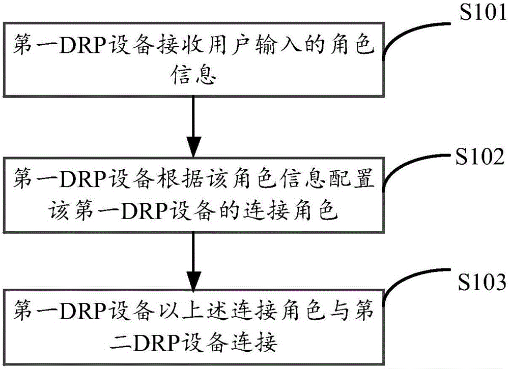
[0049] The embodiment of the present invention provides a device connection method, the specific process can refer to figure 1 , which may include the following steps:
[0050] Step 101, the first DRP device receives role information input by a user.
[0051] Wherein, the first DRP device is provided with role information for the user to select, the role information may include but not limited to: UFP and DFP, after the user inputs the selected role information on the first DRP device, the first DRP device receives the user The entered role information.
[0052]Taking the first DRP device as a mobile phone as an example, in the embodiment of the present invention, a visual user interface control switch can be added to the mobile phone. This switch can be a switch that includes two options, DFP and UFP, for the user to choose one of. . Normally, these two options cannot be enabled at the same time. After the user inputs the selected role information on the user interface, t...
Embodiment 2
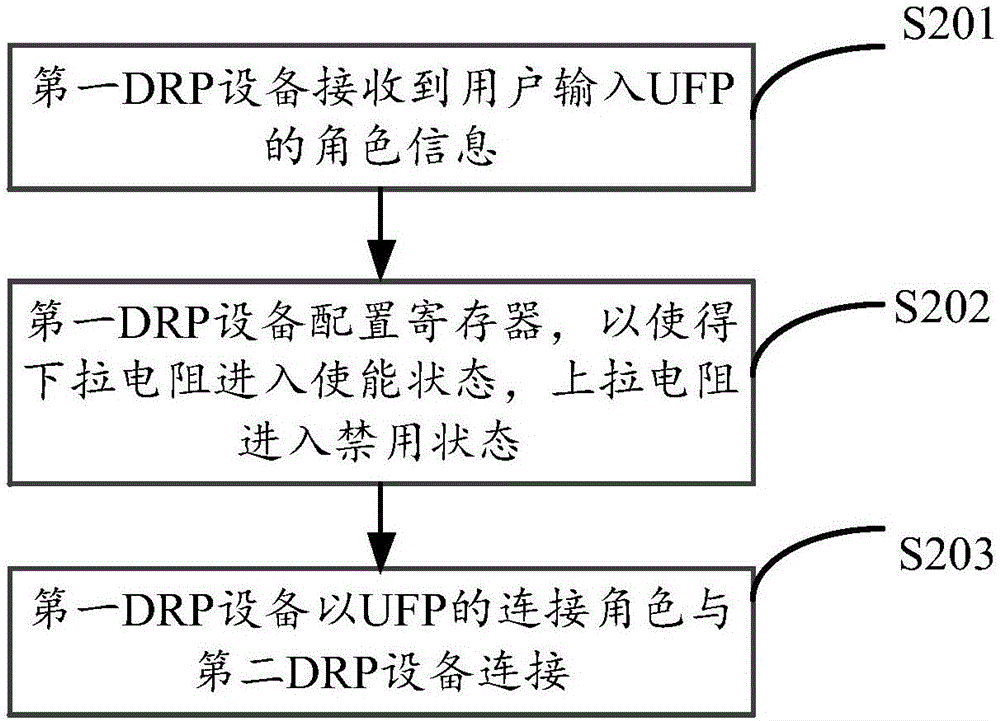
[0070] In the embodiment of the present invention, taking the role information input by the first DRP device as UFP as an example, another device connection method is provided. For the specific process, please refer to figure 2 , which may include the following steps:
[0071] Step 201, the first DRP device receives UFP role information input by the user.
[0072] Step 202, the first DRP device configures the register, so that the pull-down resistor enters an enabled state, and the pull-up resistor enters a disabled state.
[0073] The first DRP device writes and reads the register, and sets potentials for the pull-up resistor Rp and the pull-down resistor Rd in the register. When the role information entered by the user is UFP, the first DRP configures the register to set the potential for the pull-up resistor Rp and the pull-down resistor Rd, thereby starting Rp and disabling Rd. For example, configure the register and configure the corresponding potential of Rd in the reg...
Embodiment 3
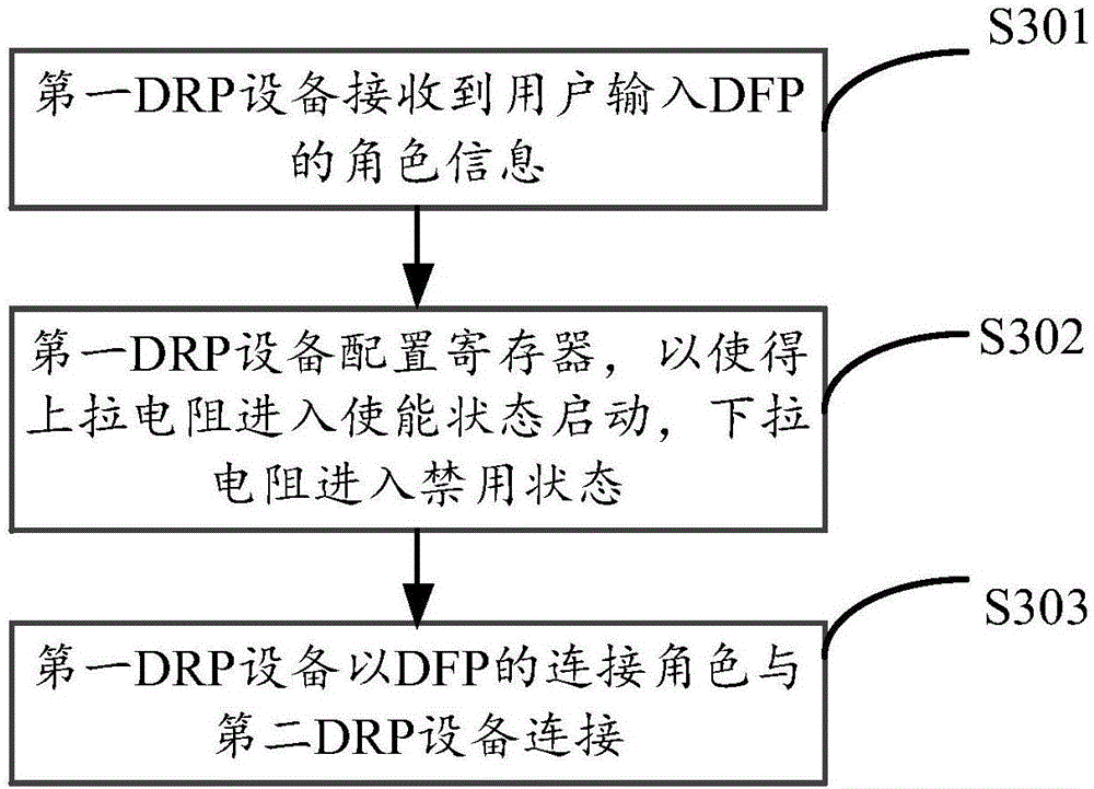
[0078] In the embodiment of the present invention, taking the role information input by the first DRP device as DFP as an example, another device connection method is provided, and its specific process can be referred to image 3 , which may include the following steps:
[0079] Step 301, the first DRP device receives the role information of the DFP input by the user.
[0080] Step 302, the first DRP device configures the register so that the pull-up resistor enters the enabled state and starts, and the pull-down resistor enters the disabled state.
[0081] The first DRP device writes and reads the register, and sets potentials for the pull-up resistor Rp and the pull-down resistor Rd in the register. When the role information entered by the user is DFP, the first DRP configuration register sets the potential for the pull-up resistor Rp and the pull-down resistor Rd, thereby starting Rp and disabling Rd, for example, configuring the register, configuring the potential corresp...
PUM
 Abstract
Description
Claims
Application Information
 - R&D
- Intellectual Property
- Life Sciences
- Materials
- Tech Scout
- Unparalleled Data Quality
- Higher Quality Content
- 60% Fewer Hallucinations
Browse by: Latest US Patents, China's latest patents, Technical Efficacy Thesaurus, Application Domain, Technology Topic, Popular Technical Reports.
© 2025 PatSnap. All rights reserved.Legal|Privacy policy|Modern Slavery Act Transparency Statement|Sitemap|About US| Contact US: help@patsnap.com