Battery device that holds batteries

a battery and battery technology, applied in the field of batteries, can solve the problems of reducing productivity, unable to provide a sufficient force, troublesome resin between batteries, etc., and achieve the effects of short battery life, efficient cooling of batteries, and even flow

Active Publication Date: 2017-01-10
TOYODA GOSEI CO LTD +1
View PDF7 Cites 1 Cited by
  • Summary
  • Abstract
  • Description
  • Claims
  • Application Information

AI Technical Summary

Benefits of technology

[0008]When being inserted in the axial direction into the space between the batteries, the restriction member receives, on its tapered surface, a reactive force from an edge of the battery and presses and supports the side face of the battery by surface contact with the support surface by this reactive force. The respective support surfaces are formed to have surface contact, so that the batteries are positioned in the axial direction by the support surfaces as reference planes. The intervals between the respective batteries are specified to be fixed by the restriction members, so that passages which a cooling medium flows through are arranged at fixed intervals. This arrangement enables the cooling medium to evenly flow between the batteries and efficiently cool down the batteries. This reduces a variation in temperature of the batteries and equalizes the temperatures of the plurality of batteries, thus preventing part of the batteries from having short battery life and extending the entire battery life.

Problems solved by technology

The battery holder according to the disclosure of JP 2012-28244A, however, has problems that the operation of filling a resin between batteries is troublesome and reduces the productivity.
This may apply a large force to part of the batteries and cause deformation or may fail to provide a sufficient force for holding part of the batteries.

Method used


Image

  • Battery device that holds batteries
  • Battery device that holds batteries
  • Battery device that holds batteries

Examples


first embodiment

A. First Embodiment

(1) Configuration of Battery Device

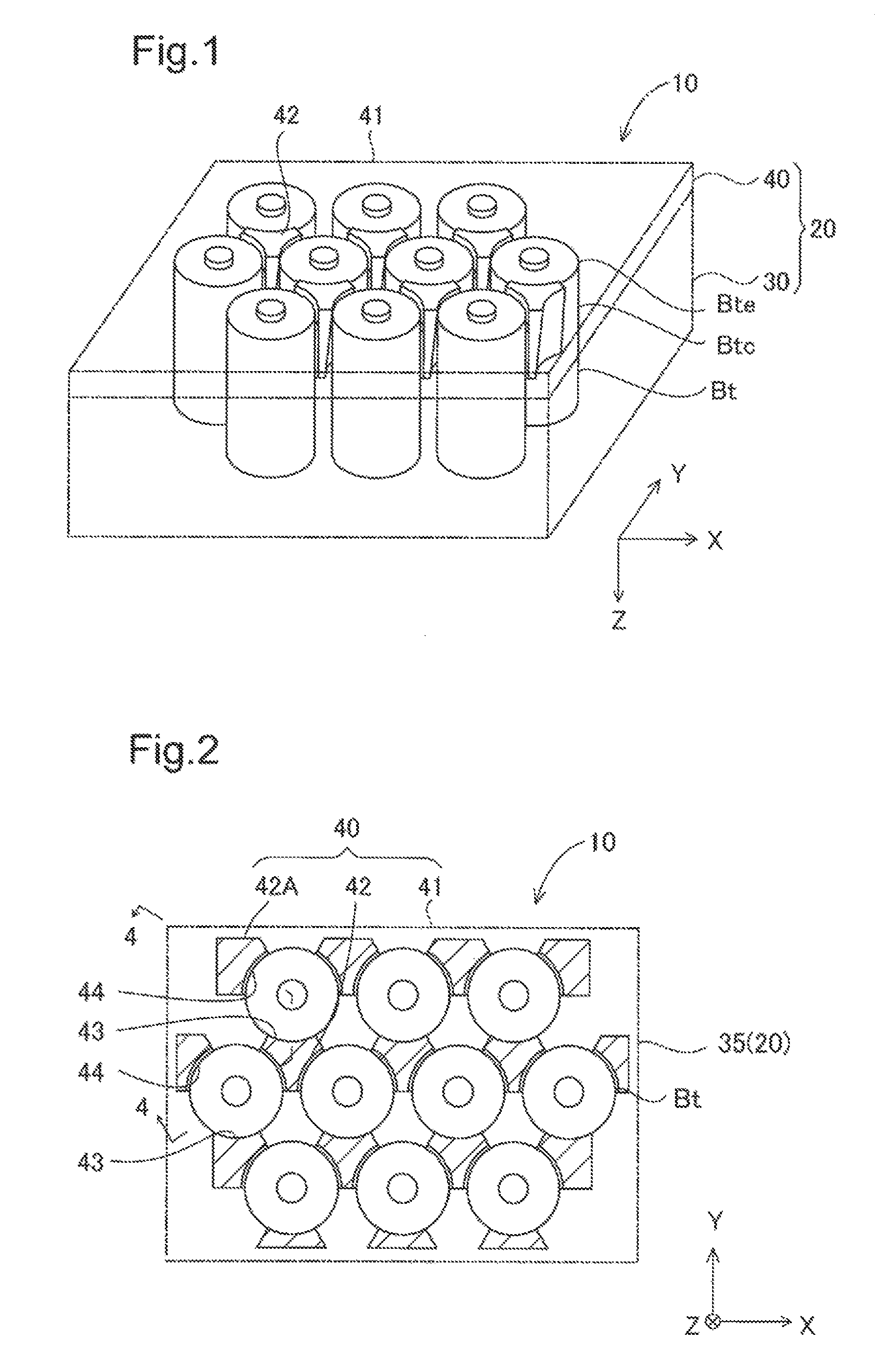
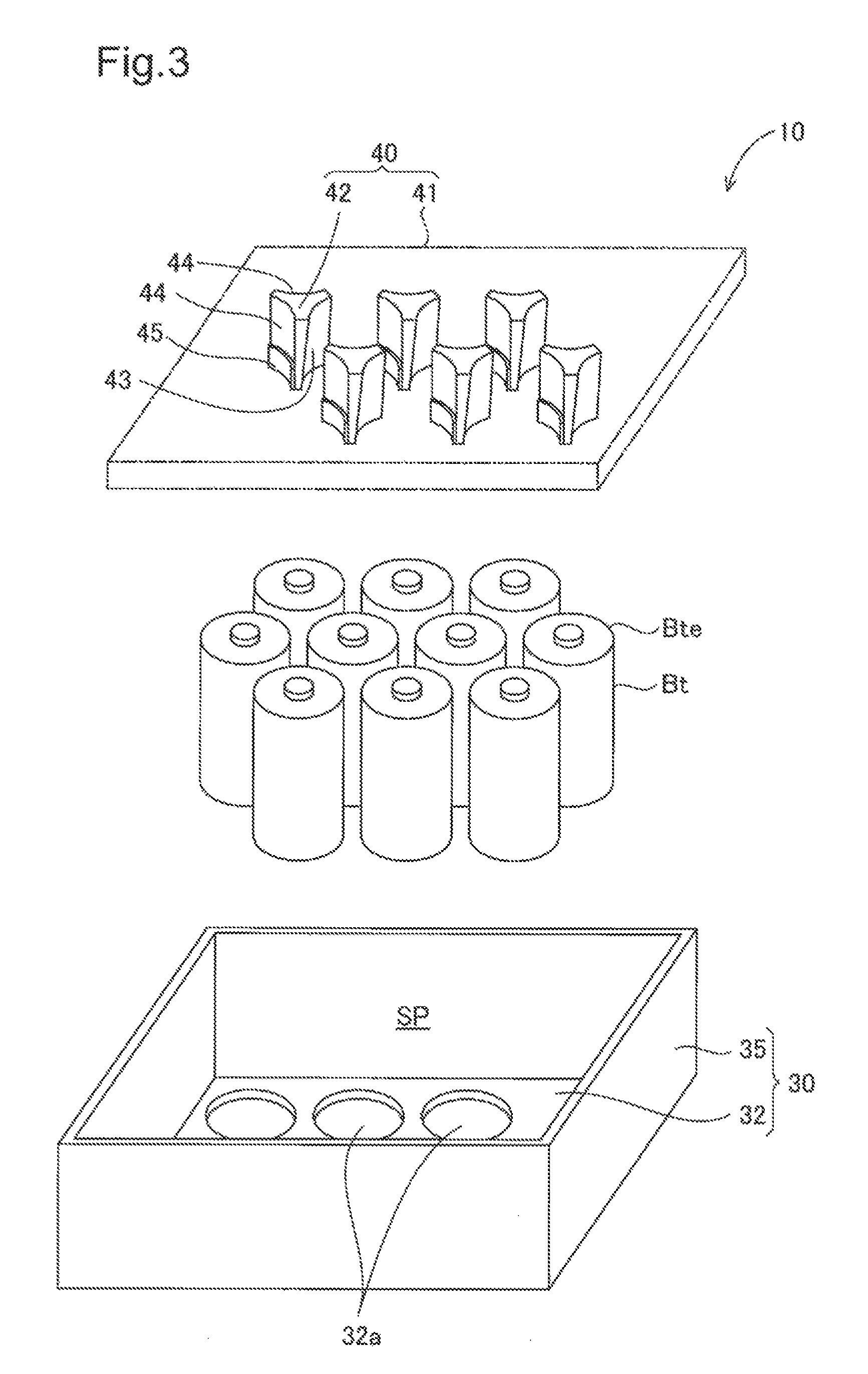
[0030]FIG. 1 is a perspective view illustrating a battery device 10 having a plurality of batteries Bt held by a battery holder 20 according to a first embodiment of the invention. FIG. 2 is a plan view of the battery device 10. The battery device 10 is configured as a mechanism to hold the plurality of batteries .Bt by the battery holder 20. The batteries Bt are cylindrical general-purpose batteries, and lithium ion batteries used as automobile power sources may be applied, to the batteries Bt. The battery Bt has a battery casing Btc in a cylindrical shape. A positive terminal and a negative terminal are respectively formed on end faces of the battery casing Btc.

[0031]XYZ axes orthogonal to one another are shown in FIG. 1. The X-axis direction is also called column direction of batteries. The Y-axis direction is a direction orthogonal to the column direction and is also called row direction of batteries. The Z-axis direction is ...

second embodiment

B. Second Embodiment

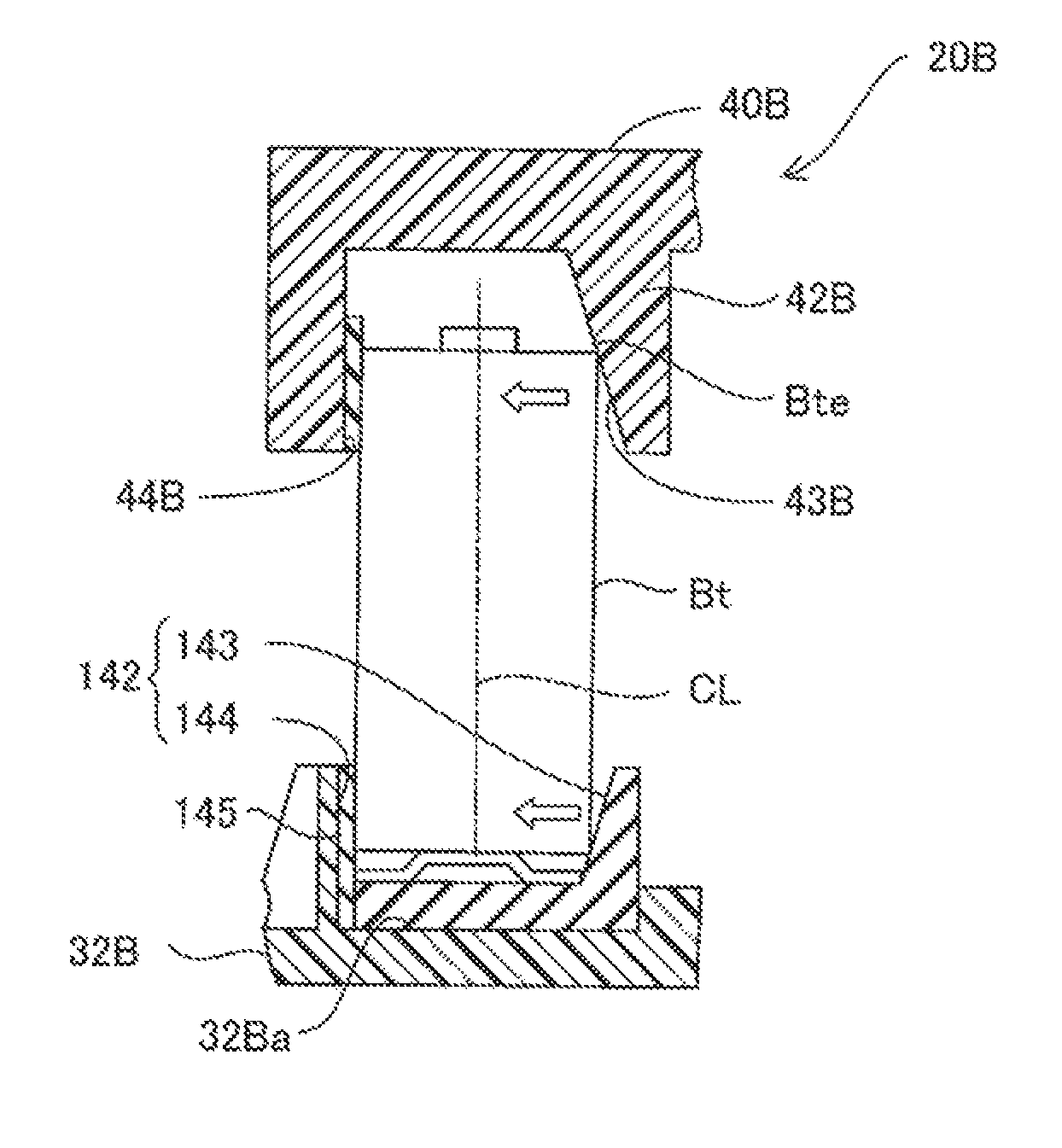
[0047]FIG. 11 is a diagram illustrating a battery holder 20B according to a second embodiment. This embodiment is characterized by the structure where a restriction member 142 is provided to support the outer periphery of the other end face of the battery Bt. FIG. 12 is overhead views of a restriction member 42B and the restriction member 142. FIG. 12(A) shows the upper restriction member 42B and FIG. 12(B) shows the lower restriction member 142. The restriction member 142 is provided in a support recess 32Ba of a bottom plate 32B and includes a tapered surface 143 and two support surfaces 144. A member having the tapered surface 143 is made of an elastic material such as rubber. The tapered surface 143 (FIG. 12(B)) is located on the same side as that of an upper tapered surface 43B (FIG. 12(A)). Members forming the support surfaces 144 shown in FIG. 11 are vertically arranged and protruded at two different positions from the upper surface of the bottom plate 32B...

third embodiment

C. Third Embodiment

[0050]FIG. 13 is a cross sectional view illustrating a battery holder 20C according to a third embodiment of the invention. This embodiment is characterized by the structure to additionally support the battery Bt on its center part. A middle support plate 170 is located between restriction members 42C and a bottom plate 32C. The middle support plate 170 has through holes 172, which the batteries Bt pass through. The through hole 172 has a gap Gp from the side face of the battery Bt. The lower part of the battery Bt is held by a support recess 32Ca of the bottom plate 32C. A bus bar 180 is placed in the support recess 32Ca. The bus bar 180 is made of a spring that presses the battery upward in the axial direction. The bus bar 180 is in electrically contact with the negative terminal of the battery.

[0051]When the battery Bt receives a tilting force, for example, during insertion operation of the restriction member 42C, the side face of the battery Bt comes into cont...


PUM

PropertyMeasurementUnit
forceaaaaaaaaaa
displacementaaaaaaaaaa
distanceaaaaaaaaaa

Abstract

A battery holder includes restriction members protruded from a holding base plate in an axial direction of batteries to be located in spaces between the batteries. Each of the restriction members has: a tapered surface which is inclined to the axial direction and is in line contact with an outer periphery of the end face of the battery when the restriction member is inserted into the space, so as to apply a force to move the battery in a radial direction of the battery; and a support surface which supports a side face of the battery that is not in contact with the tapered surface, by surface contact. The support surface receives a moving force in the radial direction from the tapered surface and supports the side face of the battery by a reactive force.

Description

CROSS-REFERENCE TO RELATED APPLICATION[0001]The present application claims the priority based on Japanese Patent Application No. 2013-59318 filed on Mar. 22, 2013, the disclosure of which is hereby incorporated by reference in its entirety.BACKGROUND[0002]1. Technical Field[0003]The present invention relates to a battery device.[0004]2. Related Art[0005]A known configuration of a battery device having a battery holder to hold a plurality of batteries fills a potting resin between batteries for modularization (see JP 2012-28244A). Another known technique attaches elastic deformable members made of an elastic material to a frame body and holds edges of batteries by the elastic deformable members (see JP 2010-9798A).[0006]The battery holder according to the disclosure of JP 2012-28244A, however, has problems that the operation of filling a resin between batteries is troublesome and reduces the productivity. In the battery holder according to the disclosure of JP 2010-9798A, on the othe...

Claims


Application Information

Patent Timeline
Patent Type & Authority Patents(United States)
IPC IPC(8): H01M2/10H01M50/213H01M50/249H01M50/289
CPCH01M2/105H01M2/1077H01M50/213H01M50/289H01M50/249Y02E60/10
Inventor TAKEDA, SHINICHIKASUYA, JINKAMEDA, YOSHIAKIKUSABA, KOSUKEKODERA, MASANORIISOGAI, YUKIHIRONORO, KAZUHIROFUJIWARA, NOBUYOSHI
Owner TOYODA GOSEI CO LTD
Why Eureka
Try Eureka