Construction technology of cantilever beam push-pull frame for jack-up drilling platform

A drilling platform and cantilever beam technology, applied in the drilling platform field, can solve the problems of manpower and material resources, inconvenient processing and high cost, and achieve the effects of reducing deformation, processing cost and processing time.

Active Publication Date: 2018-11-09
NANTONG ZHENHUA HEAVY EQUIP MFG
View PDF5 Cites 0 Cited by
  • Summary
  • Abstract
  • Description
  • Claims
  • Application Information

AI Technical Summary

Problems solved by technology

The existing technology is to carry out boring in the field after the whole is closed, which is extremely inconvenient to process, consumes a lot of manpower and material resources, and has a high cost

Method used


Image

  • Construction technology of cantilever beam push-pull frame for jack-up drilling platform
  • Construction technology of cantilever beam push-pull frame for jack-up drilling platform
  • Construction technology of cantilever beam push-pull frame for jack-up drilling platform

Examples


Embodiment Construction

[0022] The invention discloses a construction technology for a cantilever beam push-pull frame of a self-elevating drilling platform. The main steps are as follows:

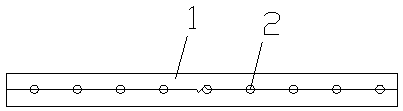
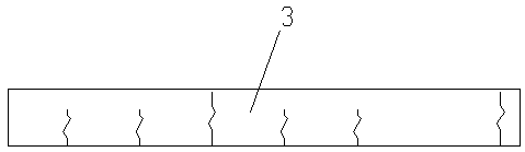
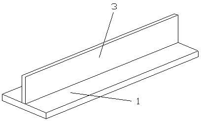
[0023] (1) Material preparation: CNC cut the main board 1 and web 3 of the push-pull frame, add 8mm allowance on one side at the long closing opening in the length direction, and add 30mm allowance at the T row closing opening; in the width direction , a 10mm margin is added on one side; a 27mm margin is added to the radial direction of the pin hole 2. Such as figure 1 , figure 2 shown.

[0024] (2) Lengthening of main board 1 and web 3: place the components on the horizontal tire frame, butt them two by two, leaving only 3mm of welding shrinkage at the closing mouth, and then open the bevel to adjust the overall straightness and flatness of the components Until it meets the requirements, then fix it with Karma. When welding, one side is grounded first, the other side is followed by root cleaning, and finall...


PUM


Abstract

A construction method for the sliding frame of a cantilever beam for a jack-up drilling rig, comprising the following steps: (1) preparing materials: CNC blanking; and adding in allowances in the directions of the length and width of the blanks, together with that of the radius of plug pin holes; (2) forming the main plate (1) and web plate (3) by way of jointing members: jointing the members together end-to-end, and forming fore, middle and aft sections; then cutting out the allowance in a widthwise direction, and cutting a slope into the web plate; (3) manufacturing a T-shaped component: assembling the main plate (1) and the web plate (3) together to form a T-shaped component; (4) machining plug pin holes (2): drawing the center lines and machining lines of the plug pin holes (2), and boring the plug pin holes (2) until the diameters thereof meet the drawing requirements; (5) closing in field: firstly determining, according to the requirement of the distance between the sliding frame and a well center line (4), the positions of the fore and aft T-shaped sections, then measuring the space between the fore and aft T-shaped sections, distributing the distance equally for middle T-shaped sections, and positioning the middle T-shaped sections. The construction method can ensure that the sliding frame meets various construction requirements while improving construction efficiency and reducing construction cost.

Description

technical field [0001] The invention relates to the technical field of drilling platforms, in particular to a construction technology for a cantilever beam push-pull frame of a self-elevating drilling platform. Background technique [0002] With the development of society and the progress of science and technology, human beings' demand for energy is also increasing. Offshore oil rigs are being built in increasing numbers, and cantilever beam rigs are popular because they can drill multiple cluster wells in one location. [0003] The hydraulic mechanism pushes and pulls the push-pull frame on the cantilever beam through the pin inserted into the pin hole to realize the extension and retraction of the cantilever beam. The manufacturing accuracy of the push-pull frame not only affects the reliability of the extension and retraction process of the cantilever beam, but also affects the smooth installation of the hydraulic push-pull mechanism. As an important structure of the ca...

Claims


Application Information

Patent Timeline
Patent Type & Authority Patents(China)
IPC IPC(8): B23P15/00
CPCB23P15/00
Inventor 林海桥曹凤丽
Owner NANTONG ZHENHUA HEAVY EQUIP MFG
Why Eureka
Try Eureka