A hydraulic power head

A hydraulic power head and linkage technology, which is applied in the direction of driving devices, metal processing machinery parts, metal processing equipment, etc., can solve the problems of large processing errors, wear and tear of rotating shafts, etc., and achieve convenient hydraulic stroke speed control valves, reduce friction, The effect of reducing the restriction of radial sliding

Active Publication Date: 2018-08-14
福州兴诺机械工业有限公司
View PDF7 Cites 0 Cited by
  • Summary
  • Abstract
  • Description
  • Claims
  • Application Information

AI Technical Summary

Problems solved by technology

A relatively simple variable speed transmission mechanism with various forms. The basic principle is that the motor drives a gear transmission mechanism, which can realize functions such as boring, milling, and drilling. Some have guide rails and can move linearly in a small range; the power head According to the feed power, it can be divided into mechanical power head and hydraulic power head. Compared with the mechanical power head, the hydraulic power head has the advantages of stable and accurate feeding. The existing hydraulic power head generally uses an external motor to drive the shaft to rotate through the pulley. The radial load on the rotating shaft will cause the rotating shaft to have a certain eccentricity during the working process, which not only causes large machining errors, but also causes rapid wear of the rotating shaft; in addition, in the actual processing process, it is often necessary to place the power head horizontally. Since the ordinary power head has only one hydraulic stroke speed regulating valve, the hydraulic stroke speed regulating valves of the two horizontally opposite power heads are respectively on different sides, and one of the hydraulic stroke speed regulating valves needs to go around the back of the machine to adjust

Method used


Image

  • A hydraulic power head
  • A hydraulic power head

Examples


Embodiment Construction

[0026] The present invention will be described in detail below with reference to the drawings and specific embodiments.

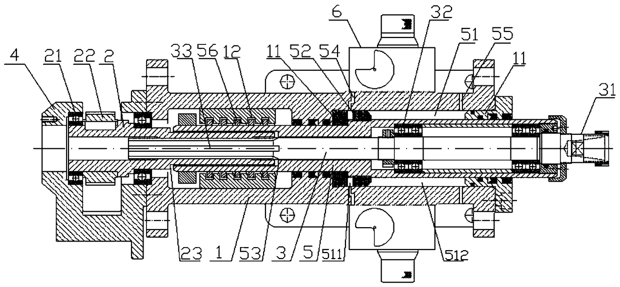
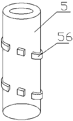
[0027] Such as figure 1 , 2 As shown, a hydraulic power head includes a housing 1 and a driving shaft sleeve 2 and a driven shaft 3 rotatably connected in the housing 1; one end of the driving shaft sleeve 2 and one end of the driven shaft 3 are axially sliding sleeved , Radial linkage rotation, the realization structure is: the outer peripheral surface of the driven shaft 3 sleeved between the driven shaft 3 and the driving shaft sleeve 2 is fixedly provided with a plurality of first sliding keys 33 along the axial direction; the inner wall of the driving shaft sleeve 2 is provided There is a sliding groove that cooperates with the first sliding key 33; in the axial direction, the first sliding key 33 is slidably connected with the sliding groove, and in the radial direction, the first sliding key 33 is embedded in the sliding groove, and the drive shaft sleev...


PUM


Abstract

The invention relates to a hydraulic power head. The hydraulic power head comprises a shell, a driving shaft sleeve and a driven shaft, wherein the driving shaft sleeve and the driven shaft sleeve are rotationally connected in the shell, one end of the driven shaft is sleeved with one end of the driving shaft sleeve in a sliding mode in the axial direction, one end of the driving shaft sleeve and one end of the driven shaft are subjected to linkage rotation in the radial direction, the other end of the driving shaft sleeve extends out of the shell, and a stabilizing sleeve is rotationally connected to the other end of the driving shaft sleeve through a first bearing; the stabilizing sleeve is fixedly connected with the shell, a synchronous belt wheel is fixedly arranged on the portion, between the stabilizing sleeve and the shell, of the driving shaft sleeve in a sleeving mode, and the synchronous belt wheel and a rotating shaft of an external motor are subjected to linkage through a synchronous belt; a drill chuck which is detachably connected with a drill bit is arranged at the other end of the driven shaft, the middle of the driven shaft is sleeved with a driven shaft sleeve, the driven shaft sleeve is fixedly arranged outside the driven shaft in a sleeving mode through multiple inner rings, and second bearings are rotationally connected in the radial direction and subjected to linkage sliding in the axial direction, wherein an outer ring of each second bearing is fixed to the inner wall of the driven shaft sleeve; and a sealed annular oil cylinder is formed by the driven shaft sleeve and the inner wall of the shell in an enclosing mode, and a piston which is fixedly arranged outside the driven shaft sleeve in a sleeving mode slides in the oil cylinder in a sealing mode.

Description

Technical field [0001] The invention relates to a hydraulic power head, which belongs to the field of processing machinery. Background technique [0002] The power head can realize the main movement and the feed movement, and has a power component for automatic workpiece circulation. A relatively simple variable speed transmission mechanism, in various forms, the basic principle is that the motor drives a gear transmission mechanism, which can realize the functions of boring, milling, drilling, etc., and some have guide rails that can move in a small range of linear motion; power head According to the feed power, it can be divided into mechanical power head and hydraulic power head. Compared with mechanical power head, hydraulic power head has the advantages of stable and accurate feeding. The existing hydraulic power head generally uses an external motor to drive the shaft to rotate through a pulley. Radial load on the rotating shaft will cause the rotating shaft to have a cert...

Claims


Application Information

Patent Timeline
Patent Type & Authority Patents(China)
IPC IPC(8): B23Q5/02B23Q5/26B23Q5/06
CPCB23Q5/02B23Q5/06B23Q5/26
Inventor 池少锋
Owner 福州兴诺机械工业有限公司
Why Eureka
Try Eureka