High-speed motorized spindle rotary structure

A high-speed motorized spindle and rotary structure technology, which is applied to large fixed members, metal processing machinery parts, metal processing equipment, etc., can solve the problems of machining error, the motorized spindle cannot dissipate heat in time, thermal deformation, etc., to reduce heat, thermal expansion, etc. The effect of coefficient reduction and weight reduction

Pending Publication Date: 2020-05-19
宁波天控五轴数控技术有限公司
View PDF0 Cites 0 Cited by
  • Summary
  • Abstract
  • Description
  • Claims
  • Application Information

AI Technical Summary

Problems solved by technology

[0004] Therefore, how to provide a high-speed electric spindle rotation structure to solve the problem of thermal deformation of the electric spindle due to the absorption of a large amount of heat energy that cannot be dissipated in time and the problem of machining errors caused by thermal deformation, and to reduce manufacturing costs, is a technical field urgent need for personnel

Method used


Image

  • High-speed motorized spindle rotary structure
  • High-speed motorized spindle rotary structure

Examples


Embodiment Construction

[0020] The following will clearly and completely describe the technical solutions in the embodiments of the present invention with reference to the accompanying drawings in the embodiments of the present invention. Obviously, the described embodiments are only some, not all, embodiments of the present invention. Based on the embodiments of the present invention, all other embodiments obtained by persons of ordinary skill in the art without making creative efforts belong to the protection scope of the present invention.

[0021] The object of the present invention is to provide a high-speed electric spindle rotation structure to solve the above-mentioned technical problems in the prior art.

[0022] In order to make the above objects, features and advantages of the present invention more comprehensible, the present invention will be further described in detail below in conjunction with the accompanying drawings and specific embodiments.

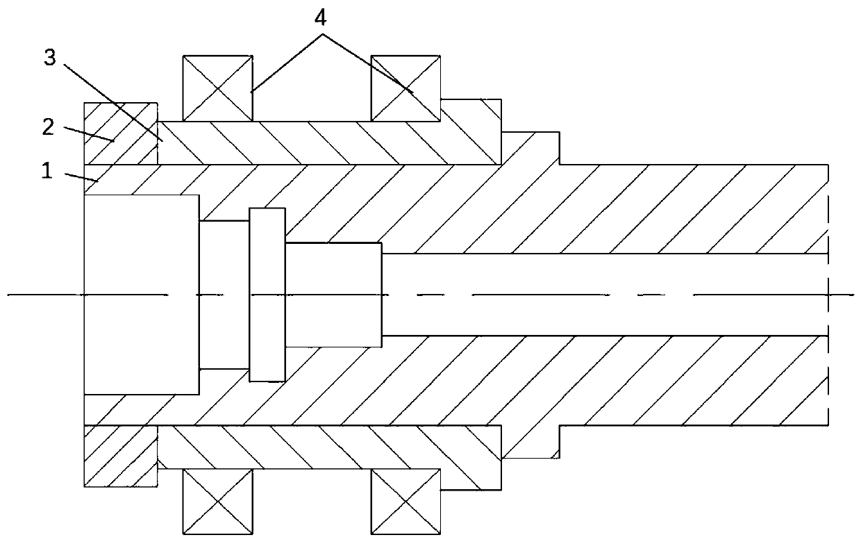
[0023] Such as figure 1 As shown, this...


PUM


Abstract

The invention discloses a high-speed motorized spindle rotary structure. The structure comprises a spindle, a carbon fiber distance ring, a positioning distance ring and a bearing. The spindle is provided with at least one shaft shoulder. The carbon fiber distance ring is mounted on the outer surface of the spindle and rotates synchronously with the spindle. One end of the carbon fiber distance ring is provided with an annular boss. The end face of the annular boss is attached to one of the at least one shaft shoulder. One end face of the positioning distance ring is fixedly connected with theend face, away from the annular boss, of the carbon fiber distance ring. The inner surface of the positioning distance ring makes no contact with the outer surface of the spindle. The bearing is mounted on the carbon fiber distance ring in an interference fit connecting mode and located on one side of the annular boss. According to the high-speed motorized spindle rotary structure, by arranging the carbon fiber distance ring, heat produced by high-speed rotation friction of the bearing is conducted to a secondary part efficiently in an axial heat conduction mode, the carbon fiber bearing distance ring is located between the bearing and the spindle, and therefore, a thermal insulation effect is achieved.

Description

technical field [0001] The invention relates to the technical field of electric spindles, in particular to a high-speed electric spindle rotation structure. Background technique [0002] With the rapid development of modern processing to high speed, the requirements for the high efficiency of the electric spindle are getting higher and higher. The electric spindle is famous for its high speed, high precision, and high dynamic and static stability. The key to realize the high speed and precision of the electric spindle is the bearing. At present, the bearings used in high-power high-speed precision electric spindles are mainly angular contact ceramic ball bearings and hydrodynamic and static pressure bearings. The bearings of most motorized spindles are directly connected to the spindle. When the spindle is running at high speed, a large amount of heat energy will be generated. These heat energy will be directly transmitted to the spindle, causing thermal elongation, thermal...

Claims


Application Information

Patent Timeline
IPC IPC(8): B23B19/02
CPCB23Q1/70
Inventor 王乐王刚戴野
Owner 宁波天控五轴数控技术有限公司
Why Eureka
Try Eureka