Current collection device and electric power transmission system

A current collector and power transmission technology, which is applied in the field of current collectors and power transmission systems, can solve problems such as the position deviation of the collector power supply circuit and the narrowing of the movable range of the collector, and achieve the effect of not being easy to contact badly

Active Publication Date: 2017-03-08
PANASONIC INTELLECTUAL PROPERTY MANAGEMENT CO LTD
View PDF6 Cites 0 Cited by
  • Summary
  • Abstract
  • Description
  • Claims
  • Application Information

AI Technical Summary

Problems solved by technology

However, if such a rotation suppressing member is provided, the movable range of the collector becomes narrow
Therefore, when a part of the longitudinal direction of the power supply circuit is locally largely displaced in a direction intersecting the longitudinal direction of the power supply circuit, the position of the current collector relative to the power supply circuit may deviate.

Method used


Image

  • Current collection device and electric power transmission system
  • Current collection device and electric power transmission system
  • Current collection device and electric power transmission system

Examples


no. 1 Embodiment approach

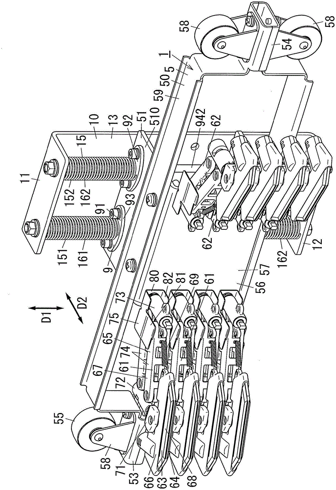
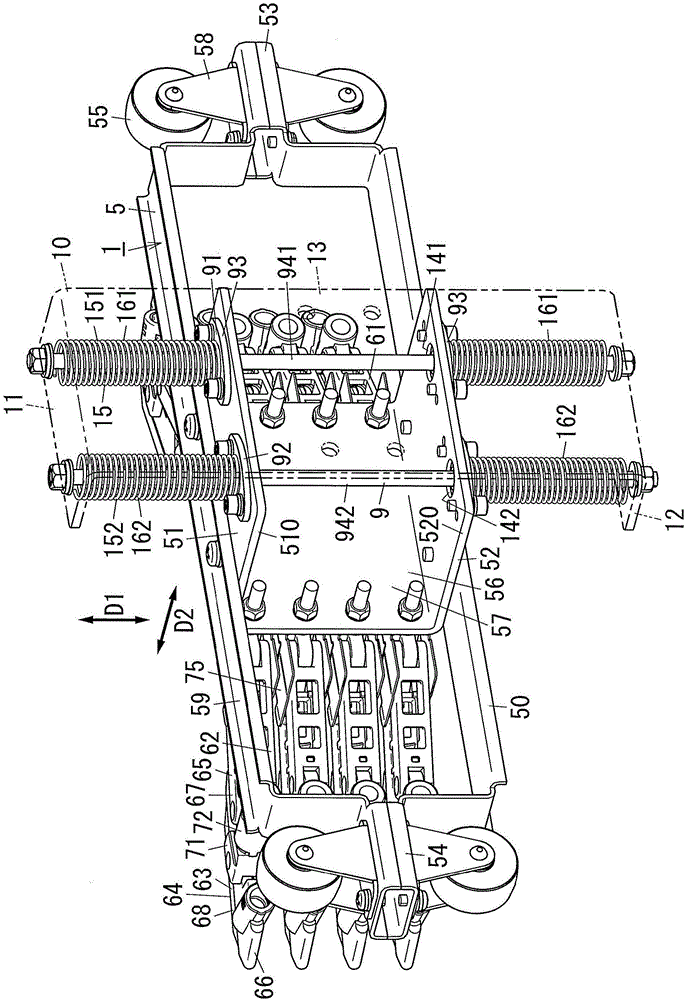
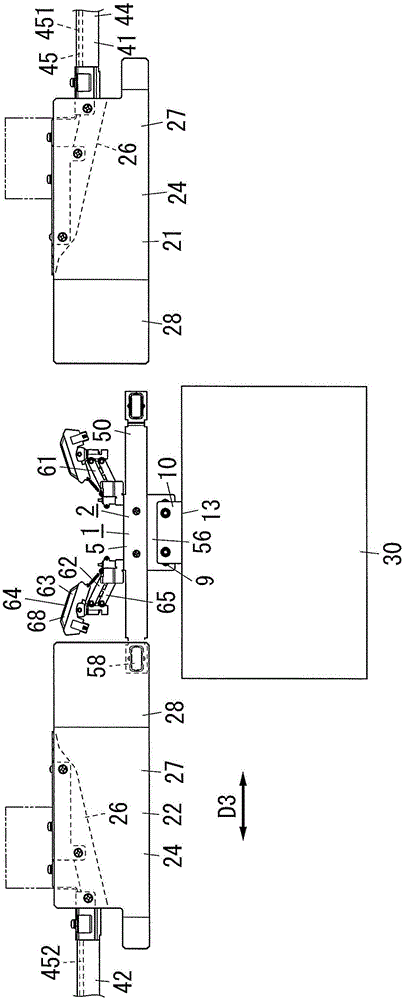
[0044] figure 1 and figure 2 It is a perspective view of the current collector 1 of this embodiment. image 3 It is a plan view showing an electric power transmission system (sliding raceway system) 2 including a power collector 1 .

[0045] The power transmission system 2 of this embodiment includes a power collector 1, a mobile device 30, and Figure 4 Multiple supply circuits 45 are shown.

[0046] A plurality of power supply circuits 45 are used as power sources for the mobile device 30 . A plurality of power supply circuits 45 are provided along the moving path of the mobile device 30 .

[0047] The plurality of power supply circuits 45 in this embodiment extend in the horizontal direction and are arranged in the vertical direction. That is, the arrangement direction D1 of the some power supply circuit 45 of this embodiment is an up-down direction. A plurality of power supply circuits 45 may also be arranged in a row in the horizontal direction. In addition, the p...

no. 2 Embodiment approach

[0158] Next, a second embodiment will be described. In the following description of the second embodiment, the same reference numerals are assigned to the same configurations as those of the first embodiment, and the description of the common content of the first embodiment will be omitted.

[0159] Such as image 3 As shown, the longitudinal direction of the first power supply rail 41 and the longitudinal direction of the second power supply rail 42 in the first embodiment are parallel when viewed in the vertical direction. On the other hand, the longitudinal direction of the second power supply rail 42 of the present embodiment is as follows: Figure 6 As shown, it is perpendicular to the longitudinal direction of the first power supply rail 41 when viewed in the vertical direction.

[0160] Such as Figure 7 As shown, the guide member 23 is provided on the second power supply rail 42 . The guide member 23 is provided at a position corresponding to the first power supply...


PUM


Abstract

The topic of the invention provides a current collection device and an electric power transmission system. The collection device and the system have the advantages that position deflection of a current collector relative to a power supply circuit, and poor contact of the current collector relative to the power supply circuit do not take place easily. The current collection device (1) provided by the invention comprises current collection arms (61, 62), a movable component (5) and a displacement mechanism (9), wherein one end of an arm (65) of the current collection arms (61, 62) is used to hold a current collector (63), and the end part opposite to the current collector (63) side is held by the movable component (5); the movable component (5) can be connected to a connection component disposed on movable equipment (30) via the displacement mechanism (9); the displacement mechanism (9) can make the movable component (5) move relative to the connection component; and the displacement mechanism (9) can limit the displacement direction of the movable component (5) relative to the connection component to be opposite to the length direction of a power supply circuit (45).

Description

technical field [0001] The invention relates to a power collecting device and a power transmission system. Background technique [0002] Japanese Patent Laid-Open No. 2008-301577 (hereinafter referred to as "Document 1") discloses a power collector that transmits electric power from a power supply circuit to mobile equipment such as a crane. This current collector includes a current collector arm and a fixing member. The collector arm includes a collector and an arm. One end of the arm holds the current collector, and the end opposite to the current collector is held by a fixing member. The current collector is mounted to the mobile device by fixing the fixing member to the mobile device. [0003] When the current collector moves together with the mobile device, the current collector moves while being in contact with the power supply circuit. Accordingly, power is collected from the power supply circuit to the collector, and the power of the power supply circuit is suppl...

Claims


Application Information

Patent Timeline
Patent Type & Authority Applications(China)
IPC IPC(8): B60L5/08
CPCB60L5/08B60L5/06B60L5/10B60L5/30B60L5/36
Inventor 土岐政人
Owner PANASONIC INTELLECTUAL PROPERTY MANAGEMENT CO LTD
Why Eureka
Try Eureka