Method for soldering interconnectors to photovoltaic cells

A solar cell and soldering technology, which is applied in electrical components, circuits, photovoltaic power generation, etc., can solve the problems of high cost of solar cells, no disclosure of solutions, rupture of solar cells, etc., so as to reduce the compression of bonding wires. The effect of strength, not easy to position deviation, and beautiful appearance

Inactive Publication Date: 2008-10-08
NISSHINBO IND INC
View PDF2 Cites 0 Cited by
  • Summary
  • Abstract
  • Description
  • Claims
  • Application Information

AI Technical Summary

Problems solved by technology

In a unit of approximately 150 mm square, warpage of approximately 6 to 10 mm occurs, and cracking occurs due to the warping
[0012] Furthermore, if a solar battery cell deformed such as warping occurs is processed into a solar cell panel, the deformation is mechanically corrected during processing, and it not only acts as a stress on the cell and causes cracks, but also acts as a stress on the next cell. Cracks also occur when transporting deformed solar cells such as warping during the process
[0013] Since the cost of solar battery cells is very high in solar cells, the occurrence of defective products due to cracks not only lowers productivity, but also leads to a problem of increasing loss costs.
[0014] Soldering methods are disclosed in Patent Documents 1 and 2, but there is no disclosure of a solution to the above-mentioned problems.

Method used


Image

  • Method for soldering interconnectors to photovoltaic cells
  • Method for soldering interconnectors to photovoltaic cells
  • Method for soldering interconnectors to photovoltaic cells

Examples


Embodiment approach 1

[0054] The first embodiment of the cooling mechanism after the solder has been melted will be described.

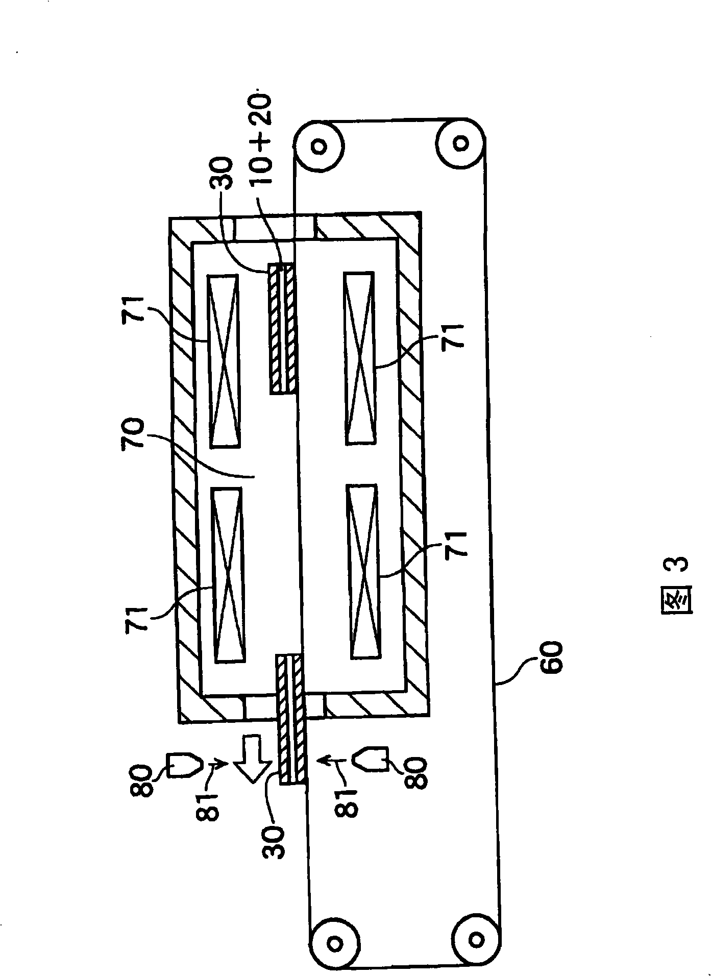
[0055] The cooling mechanism 80 provided above and below the outlet of the heating space 70 cools the solar cells 10 on the transport holder 30 sent from the heating space 70 by the conveyor belt 60 of FIG. 3, and the molten solder of the bonding wire 20 22 starts curing from the end of the solar cell unit 10. In this way, the conveyance holder 30 is conveyed by the conveyer belt 60, and the solar battery cells 10 are sequentially cooled from the end by the cooling mechanism 80. In addition, in this embodiment, cold air 81 is used as the cooling mechanism 80. As shown in FIG. 3, the cold air 81 is blown from a blowing outlet such as a nozzle attached to the outlet of the heating space 70. In this case, not only the cold air 81 is blown from above, but also the cold air 81 is blown from the lower side.

[0056] The blowing outlet 82 provided above and below the outlet of the h...

Embodiment approach 2

[0058] The second embodiment of the cooling mechanism after the solder has been melted will be described. In this embodiment, the air outlet 82 provided above and below the outlet of the heating space 70 is as Figure 6 As shown, the front end thereof traverses the entire width of the solar cell unit 10 and is formed into a shape that shrinks toward the bonding wire 20.

Embodiment approach 3

[0060] The third embodiment of the cooling mechanism after the solder has been melted will be described. In this embodiment, due to the temperature distribution of the unit 10, etc., the air outlet at the front end is as Figure 7 As shown, it is formed into a plurality of blowout ports, and each blowout port is provided with a regulating valve 83 to adjust the flow rate of the cold air.

[0061] use Figure 8 Describes how to use such a cooling mechanism 80 to solidify the bonding wire 20 on the solar cell unit 10.

[0062] Figure 8 Is a cross-sectional view of the bonding wire 20 during cooling, Figure 8 (a) is the case where the cooling is gradually carried out in a normal atmosphere, Figure 8 (b) is the case where the cooling mechanism 80 is used to perform cooling sequentially from the end of the unit.

[0063] in Figure 8 In (a), since the cooling is gradually performed, the cooling of the bonding wire 20 proceeds from the both ends of the unit to the center. In addition, du...


PUM


Abstract

A method and apparatus for soldering interconnectors to photovoltaic cells that, after soldering, prevents bending of the photovoltaic cells due to heat warping caused by heat contraction of the lead wires. The interconnectors are positioned at predetermined positions on the photovoltaic cell, the interconnectors and the photovoltaic cells are held tightly together, and the solder is melted as the photovoltaic cells are heated, after which the photovoltaic cells are sequentially cooled in the long direction of the interconnectors with cold blasts from the end of the photovoltaic cells in the long direction of the interconnector.

Description

Technical field [0001] The present invention relates to a method of soldering tab leads to solar battery cells (hereinafter, sometimes simply referred to as "cells") forming the solar cell panels in the manufacture of solar cell panels. Background technique [0002] The bonding wire fixed to the solar cell is composed of a copper wire and a solder coated with the wire. [0003] Conventionally, when a bonding wire is fixed to a solar battery cell, the bonding wire is heated while being pressed and supported by a rod-shaped or rod-shaped rigid pressing member on the unit to melt the solder of the bonding wire, thereby bonding the wire Of soldering. [0004] Such techniques are disclosed in Patent Documents 1 and 2. [0005] [Patent Document 1] JP 11-87756 A [0006] [Patent Document 2] JP 2003-168811 A [0007] When soldering the bonding wire to the solar battery cell, the heated solar battery cell is cooled by keeping it away from the heating source (heater, etc.), or blowing air ...

Claims


Application Information

Patent Timeline
Patent Type & Authority Applications(China)
IPC IPC(8): H01L31/18
CPCH01L31/0504Y02E10/50H01L31/188H01L31/05H01L31/18
Inventor 片山学市村光
Owner NISSHINBO IND INC
Why Eureka
Try Eureka