Method And Apparatus For Manufacturing Glass Substrate

A technology for glass substrates and manufacturing methods, applied to glass manufacturing equipment, glass molding, glass molding, etc., to achieve the effect of suppressing plate thickness deviation

Inactive Publication Date: 2017-03-08
AVANSTRATE INC +1
View PDF8 Cites 2 Cited by
  • Summary
  • Abstract
  • Description
  • Claims
  • Application Information

AI Technical Summary

Problems solved by technology

In particular, the central part of the molded body in the longitudinal direction tends to sag downward due to creep deformation and bend

Method used


Image

  • Method And Apparatus For Manufacturing Glass Substrate
  • Method And Apparatus For Manufacturing Glass Substrate
  • Method And Apparatus For Manufacturing Glass Substrate

Examples


Embodiment Construction

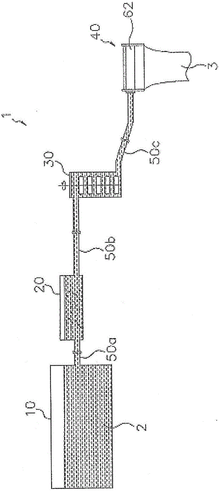
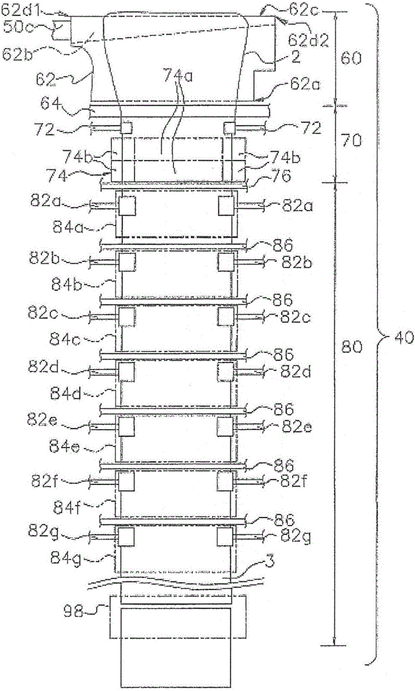
[0052] (1) Configuration of glass substrate manufacturing equipment

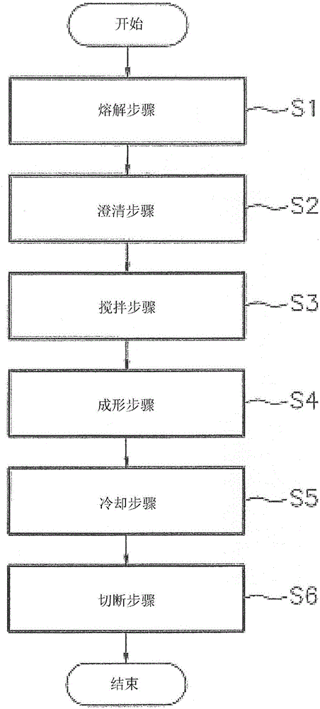
[0053] Embodiments of the manufacturing method and manufacturing apparatus of the glass substrate of this invention are demonstrated, referring drawings. figure 1 It is a flowchart which shows an example of the manufacturing method of the glass substrate of this embodiment.

[0054] Such as figure 1 As shown, the manufacturing method of the glass substrate of this embodiment mainly includes a melting step S1, a clarification step S2, a stirring step S3, a forming step S4, a cooling step S5, and a cutting step S6.

[0055] In melting process S1, glass raw material is heated and molten glass is obtained. The molten glass is stored in a melting tank, and is heated by electricity so as to have a desired temperature. Add fining agent to glass raw materials. From the viewpoint of reducing the environmental load, using SnO 2 as a clarifying agent.

[0056] In clarification process S2, molten glass is clarifie...


PUM

PropertyMeasurementUnit
widthaaaaaaaaaa
lengthaaaaaaaaaa
thicknessaaaaaaaaaa

Abstract

The invention relates to a method and apparatus for manufacturing glass substrates. The invention aims at providing a method for manufacturing the glass substrates, in order to inhibit deformation of glass ribbons (glass substrates) due to creep deformation of formed body. The method for manufacturing the glass substrates comprises the following steps: a forming step: providing molten glass for a supply groove formed on the upper surface of the formed body, molten glass which flows down at double sides of the supply groove flows down along double sides of the formed body, and molten glass which flows at double sides flow together at the lower end of the formed body in order to form the glass ribbons; a control step: according to shape change of the formed body generated by usage of the formed body, double side parts of width direction of the glass ribbons after the forming step are cooled, and tension of width direction of the glass ribbons are applied.

Description

technical field [0001] The invention relates to a manufacturing method of a glass substrate and a manufacturing device of the glass substrate. Background technique [0002] Glass substrates used in flat panel displays (FPDs) such as liquid crystal displays and plasma displays require high flatness on the surface. Typically, such glass substrates are produced by an overflow down-draw method. In the overflow downdraw method, as described in Patent Document 1, molten glass flowing into a groove on the upper surface of a molded body and overflowing from the groove flows down along both sides of the molded body and joins at the lower end of the molded body to form a glass ribbon. The formed glass ribbon is gradually cooled while being stretched downward. The cooled glass ribbon is cut into a predetermined size to obtain a glass substrate. [0003] [Background Art Document] [0004] [Patent Document] [0005] [Patent Document 1] US Patent No. 3,338,696 Contents of the inven...

Claims


Application Information

Patent Timeline
Patent Type & Authority Applications(China)
IPC IPC(8): C03B17/06
CPCC03B17/06
Inventor 中嶋公彦
Owner AVANSTRATE INC
Why Eureka
Try Eureka