clothes dryer

A technology for clothes dryers and drying barrels, which is applied in the field of clothes dryers, and can solve the problems of inconvenient cleaning of the filter device of clothes dryers by itself

Active Publication Date: 2019-09-20
BSH ELECTRICAL APPLIANCES JIANGSU +1
View PDF5 Cites 0 Cited by
  • Summary
  • Abstract
  • Description
  • Claims
  • Application Information

AI Technical Summary

Problems solved by technology

[0008] The present invention provides a clothes dryer to at least solve the problem in the prior art that the clothes dryer is inconvenient to clean the filter device by itself

Method used


Image

  • clothes dryer
  • clothes dryer
  • clothes dryer

Examples


Embodiment Construction

[0034] The following will describe in detail with reference to the drawings and embodiments, and the embodiments in the present application and the features in the embodiments can be combined without conflict.

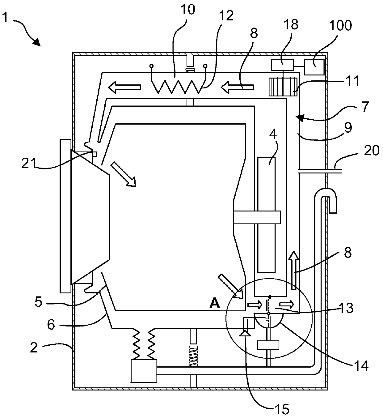
[0035] figure 1 For a side view of a clothes dryer, such as figure 1 As shown, the clothes dryer 1 has a cabinet 2, an inner tub 5 located in the cabinet 2 and driven by a main motor 4 to rotate, and an outer tub 6 (ie, a drying tub) set outside the inner tub 5 . The outer tub 6 is connected to the air channel 9 of the condensing device 7 and communicated in space. The air channel 9 of the condensing device further connects the fan 11 and the air heating channel 10 in sequence. The other end of the air heating channel 10 is then in spatial communication with the tub 6 .

[0036] In the drying process, the heater 12 (heating device) in the air heating channel 10 heats the drying air 8 flowing through it; the heated high-temperature drying air 8 enters the inner barre...


PUM


Abstract

The invention discloses a clothes dryer, which has a drying bucket and an air pipeline connected with the drying bucket, and further includes: a cavity arranged on the wall of the air pipeline; a flushing device arranged in the cavity; The baffle is divided into a filter screen of a first part and a second part; wherein, the first part and the second part are respectively located in the air duct and the cavity; the baffle isolates the cavity from the air duct, The filter screen moves to exchange the spatial positions of the first part and the second part. The present invention solves the problem of inconvenient self-cleaning of the filter device of the clothes dryer in the prior art. On the one hand, the filter screen can be cleaned by itself during the drying process without interfering with the operation of the machine; on the other hand, it is convenient for the user to operate when the machine is working Clean up foreign matter such as lint after filtering.

Description

[0001] 【Technical field】 [0002] The invention relates to a machine capable of drying clothes, in particular to a filter device of the machine. [0003] 【Background technique】 [0004] Clothes dryers generally include machines with pure dryer functions as well as machines that combine washing and drying functions. The drying principle of the clothes dryer can be roughly summarized as follows: under the action of the heating device, the dry air is heated by the heating device to form dry hot air, and then enters the drying barrel to exchange heat with the wet clothes, and the clothes in the clothes The moisture is taken away to form relatively humid hot air, which is then condensed by the condensing device, and the moisture in it is condensed into water, and then discharged through the drain pipe, and the condensed air becomes relatively dry cold air , under the action of the fan, it is redirected to the heating device, and the heated and dried hot air enters the next cycle, a...

Claims


Application Information

Patent Timeline
Patent Type & Authority Patents(China)
IPC IPC(8): D06F58/22D06F58/28D06F58/45
CPCD06F58/22D06F2105/58D06F58/45D06F2105/34D06F2103/42D06F2103/30
Inventor 朱伟洪张琦
Owner BSH ELECTRICAL APPLIANCES JIANGSU
Why Eureka
Try Eureka