Eureka AIR delivers breakthrough ideas for toughest innovation challenges, trusted by R&D personnel around the world.

Infrared induction type LED (Light-Emitting Diode) ceiling lamp

An LED ceiling lamp and infrared sensing technology, applied in the field of LED lighting, can solve the problems of slow unsatisfactory, quiet environment noise pollution, living environment damage, etc., and achieve the effect of reducing power consumption, simple and reliable structure, and high degree of intelligence

Inactive Publication Date: 2017-03-08
NANJING ROUTER SOFTWARE
View PDF5 Cites 2 Cited by
  • Summary
  • Abstract
  • Description
  • Claims
  • Application Information

AI Technical Summary

Problems solved by technology

Of course, this product has indeed achieved the purpose of energy saving to a certain extent, but at the same time it has also caused certain damage to people's living environment.
Due to the limitation of the performance of the product itself, the realization of this kind of sound and light control lamps and automatic switch control requires the cooperation of sound (over 60 decibels), which will cause a certain amount of noise pollution to the quiet environment required by the public
With the development of society and people's attention to the ecological environment, this kind of acousto-optic control lamps and switches can no longer meet people's needs, which requires the emergence of more energy-saving and environmentally friendly automatic lighting control products to meet people's high demand. quality of life needs

Method used


Image

  • Infrared induction type LED (Light-Emitting Diode) ceiling lamp
  • Infrared induction type LED (Light-Emitting Diode) ceiling lamp
  • Infrared induction type LED (Light-Emitting Diode) ceiling lamp

Examples


Embodiment Construction

[0014] In order to deepen the understanding and knowledge of the present invention, the present invention will be further described and introduced in conjunction with the accompanying drawings.

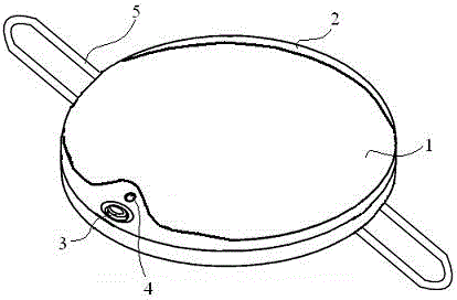
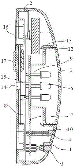
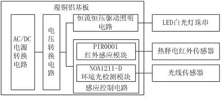
[0015] Such as figure 1 — image 3 , An infrared induction type LED ceiling lamp, including a light-transmitting cover 1, a round plastic lamp housing 2, a spring ceiling buckle 5, a pyroelectric infrared sensor 3, a copper-clad aluminum substrate 7, a number of white LED lamp beads 6 And light sensor 4. The spring ceiling buckles 5 are arranged at both ends of the bottom of the circular plastic lamp housing 2 for fixing the ceiling lamp and the ceiling. The translucent cover 1 is clamped on the top mounting slot of the circular plastic lamp housing 2 for transmitting the light emitted by the LED light source. On both sides of the light-transmitting cover 1, there are chucking lugs 12 protruding outward, and on the edge of the top mounting groove of the circular plastic lamp housing 2,...


PUM


Abstract

The invention relates to an infrared induction type LED (Light-Emitting Diode) ceiling lamp. The infrared induction type LED ceiling lamp comprises a light transmitting cover, a circular plastic lamp shell, spring ceiling buckles, a pyroelectric infrared sensor, a copper-clad aluminium substrate, a plurality of LED white light lamp beads and a light sensor; the spring ceiling buckles are arranged at the two ends of the bottom of the circular plastic lamp shell; the light transmitting cover is clamped on a mounting groove in the top of the circular plastic lamp shell; the LED white light lamp beads, the pyroelectric infrared sensor and the light sensor are all welded on the copper-clad aluminium substrate; a plurality of first accommodating holes corresponding to the LED white light lamp beads are formed in the inside wall of the light transmitting cover; a second accommodating hole and a third accommodating hole are formed in the top of the circular plastic lamp shell; the light sensor is arranged in the second accommodating hole in a sleeving manner and is exposed at the top of the circular plastic lamp shell; and the pyroelectric infrared sensor is arranged in the third accommodating hole in a sleeving manner and is exposed at the top of the circular plastic lamp shell. The LED ceiling lamp is convenient to mount and dismount, and is safe, energy-saving and environment-friendly; and intelligent lighting functions of turning on the lamp when a person comes and turning off the lamp when the person leaves can be realized.

Description

Technical field [0001] The invention belongs to the technical field of LED lighting, and particularly relates to an LED lamp, in particular to an infrared induction type LED ceiling lamp. Background technique [0002] With the continuous improvement of people's living standards, the requirements for intelligent lighting lamps are getting higher and higher. In order to facilitate the control of lighting lamps and save electricity, traditional lighting lamps use voice control to realize people come to light and people walk. Light off function. Of course, this product does achieve the purpose of energy saving to a certain extent, but it also causes some damage to people's living environment. Due to the limitation of the performance of the product itself, the realization of this kind of sound and light control lamps and switch automatic control requires the cooperation of sound (over 60 decibels), which causes certain noise pollution to the quiet environment required by the public. ...

Claims


Application Information

Patent Timeline
Patent Type & Authority Applications(China)
IPC IPC(8): F21S8/04F21V23/00F21V23/04F21V19/00F21V17/10F21V17/16H05B33/08F21Y115/10H05B44/00
CPCF21S8/04F21V17/10F21V17/162F21V19/001F21V23/003F21V23/0464F21V23/0471H05B45/00
Inventor 黄飞跃
Owner NANJING ROUTER SOFTWARE
Why Eureka
Eureka Blog
Learn More