
Stereo buffering method

A buffering method and three-dimensional technology, applied in the field of buffering, can solve the problems of waiting for the next process line, incongruity, and inconsistent processing progress, so as to solve the incongruity phenomenon and improve the work efficiency.

Active Publication Date: 2021-04-02
北京源著智能科技有限公司
View PDF10 Cites 0 Cited by
  • Summary
  • Abstract
  • Description
  • Claims
  • Application Information

AI Technical Summary

Problems solved by technology

[0004] The processing progress of each process line is sometimes inconsistent. Therefore, it often happens that the latter process line has not been processed yet, while the previous process has completed processing. In this case, the previous process line needs to wait The case of the next process line
On the other hand, the processing progress of each process line is not fixed, and sometimes the processing progress fluctuates depending on the workpiece being processed, which will also lead to inconsistency among the various processes, and this incoordination The phenomenon will affect the operating efficiency of the entire production line

Method used


Image

  • Stereo buffering method
  • Stereo buffering method
  • Stereo buffering method

Examples


Embodiment 1

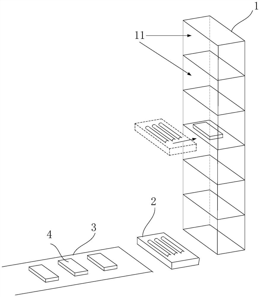
[0028] like Figure 1 to Figure 3 As shown, it is a schematic structural diagram of the three-dimensional buffer device according to the first embodiment of the present invention, and the three-dimensional buffer device includes:

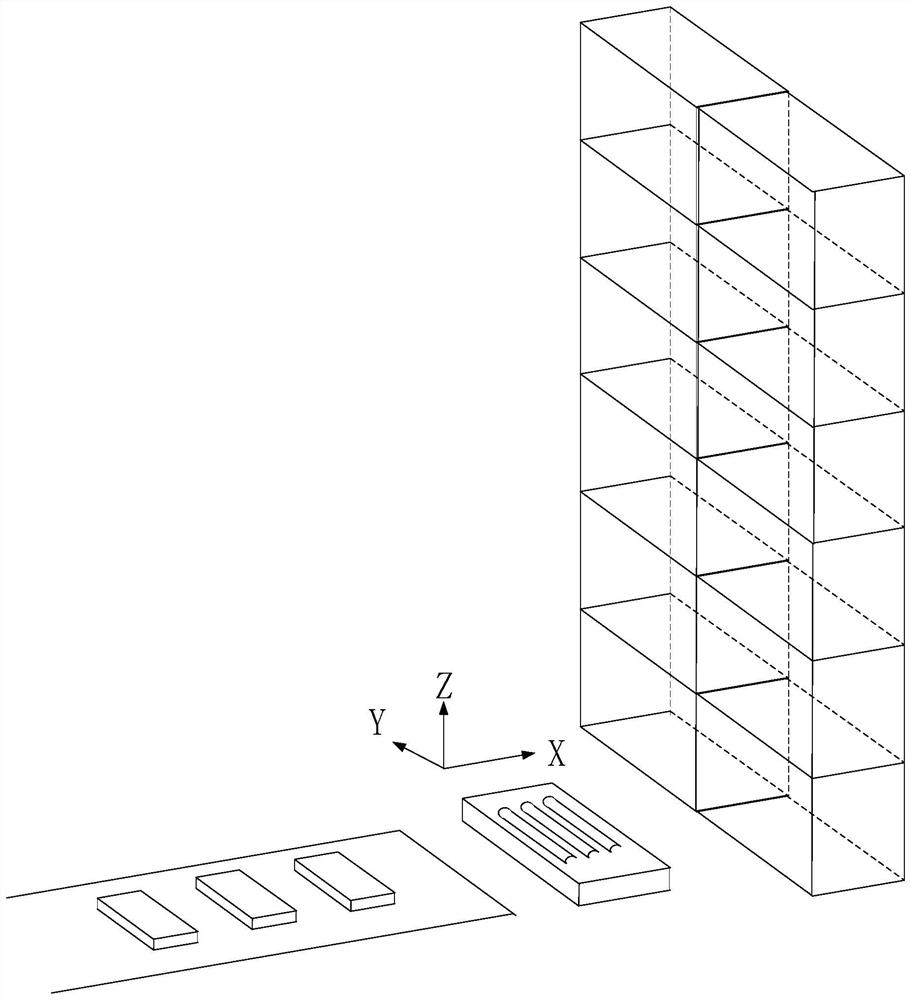
[0029] The three-dimensional storage device 1 includes a plurality of workpiece storage units 11 for storing workpieces. Wherein, the three-dimensional storage device may be such as figure 1 The shown is composed of multi-layer grid-shaped storage spaces arranged vertically, and each layer is provided with a workpiece storage unit. In addition, the workpiece storage unit 11 can also be figure 2 The one shown in is composed of a multi-layer structure, and each layer has a plurality of workpiece storage units 11 in the horizontal direction. Each workpiece storage unit can store one or more workpieces 4 , and the shape of the workpiece is not limited as long as it can be put into the workpiece storage unit 11 .

[0030] The bridging part 2 is conne...

Embodiment 2

[0036] like Figure 4 As shown, it is a schematic structural diagram of the three-dimensional buffer device according to the second embodiment of the present invention. In this embodiment, the workpiece storage unit 11 has a front and rear through structure, and the three-dimensional buffer device is arranged on the first process line 31 and the second process line 32. In between, the three-dimensional buffer device is butted with the first process line 31 and the second process line 32 .

[0037] The bridging part includes a first bridging part 21 provided on the inlet side of the three-dimensional storage device 1 and a second bridging part 22 provided on the outlet side of the three-dimensional storage device, and the first bridging part 21 is used for receiving The workpiece of the first process line 31 is stored in the workpiece storage unit of the three-dimensional storage device, and the second bridge portion 22 is used to extract the workpiece from the workpiece storag...

Embodiment 3

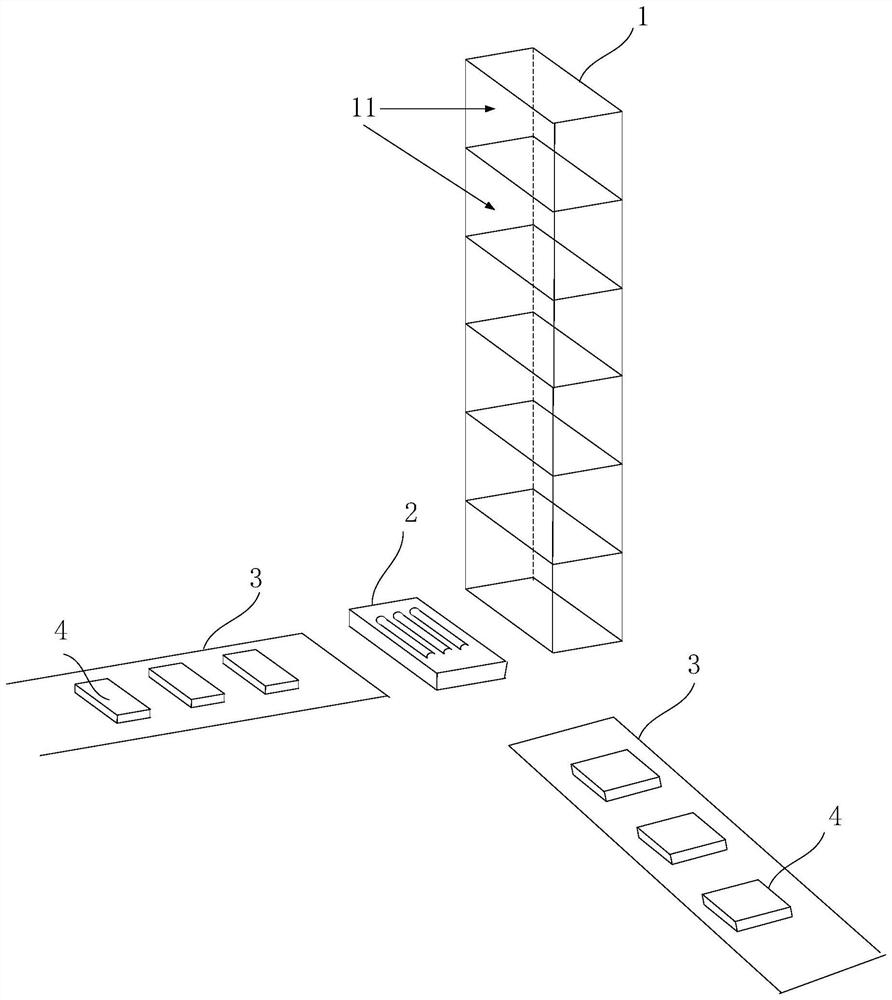
[0040] like Figure 5 As shown, it is a schematic diagram of the three-dimensional structure of the three-dimensional buffer device according to the third embodiment of the present invention. In this embodiment, in this embodiment, the three-dimensional buffer device is connected to a plurality of process lines, and the bridge portion is a plurality of , wherein there is at least one bridge 2 for receiving workpieces of a given process line 3 and storing the workpieces in the workpiece storage unit 11 of the stereo storage device 1 , and at least one bridge 2 for receiving the workpiece from the stereo storage device 1 The workpiece storage unit 11 picks up the workpiece and transfers it to another designated process line 3 . As shown in the figure, the three-dimensional buffer device of this embodiment can provide a buffer mechanism for workpiece processing for multiple process lines, and through the coordinated processing of at least two bridge parts, storage and storage are...


PUM


Abstract

The embodiment of the invention provides a three-dimensional buffering method. The three-dimensional buffering method is characterized in that a three-dimensional storing device is arranged between a first process line and a second process line, wherein the three-dimensional storing device comprises a plurality of workpiece storing units for storing workpieces. The method comprises the following steps: storing the workpieces output by the first process line to the workpiece storing units of the three-dimensional storing device according to a preset storing strategy; and picking the workpieces from the workpiece storing units of the three-dimensional storing device according to a preset picking strategy, and inputting to the second process line. According to the three-dimensional buffering method of the embodiment, the workpieces are picked and stored through the three-dimensional storing devices used for storing the workpieces according to the reasonable storing strategy and picking strategy during the processing, and a buffering area is formed between the process lines, so that the incongruity caused by mismatching or fluctuation of the processing and treatment progress of the processing lines can be solved, and as a result, the working efficiency of the whole production line can be improved.

Description

technical field [0001] Embodiments of the present invention relate to a buffering method, and in particular, to a three-dimensional buffering method for workpiece machining. Background technique [0002] In the field of automated machining, the production line generally consists of multiple process lines, each process line completes a processing task, and then the processed workpiece is transferred to the next process line, and each process line is streamlined Operation. [0003] In the process of realizing the present invention of the inventor, it is found that the prior art has the following defects: [0004] The processing progress of each process line is sometimes inconsistent. Therefore, it often occurs that the previous process line has been processed because the latter process line has not been processed yet. In this case, the previous process line needs to wait. The case of the latter process line. On the other hand, the processing progress of each process line is...

Claims


Application Information

Patent Timeline
Patent Type & Authority Patents(China)
IPC IPC(8): B23Q7/14
CPCB23Q7/14
Inventor 蔡献峰崔战伟
Owner 北京源著智能科技有限公司
Learn More