Automatic feeding device for upper cover shell of charger

A technology of automatic feeding and charging, applied in vibration conveyors, transportation and packaging, conveyors, etc., can solve the problems of low production efficiency, unstable product quality, and high labor intensity of workers

Active Publication Date: 2017-03-15
威海志航机电科技有限公司
View PDF10 Cites 4 Cited by
  • Summary
  • Abstract
  • Description
  • Claims
  • Application Information

AI Technical Summary

Problems solved by technology

[0005] The present invention aims at the technical problems of low production efficiency, unstable product quality, poor product consistency, high labor intensity and inability to realize automatic mass production in the existing manual production method of chargers, and provides a battery with high production efficiency and stable product quality. , Good product consistency, low labor intensity of workers, automatic charging device for the top cover of the charger that can realize automatic mass production

Method used


Image

  • Automatic feeding device for upper cover shell of charger
  • Automatic feeding device for upper cover shell of charger
  • Automatic feeding device for upper cover shell of charger

Examples


Embodiment 1

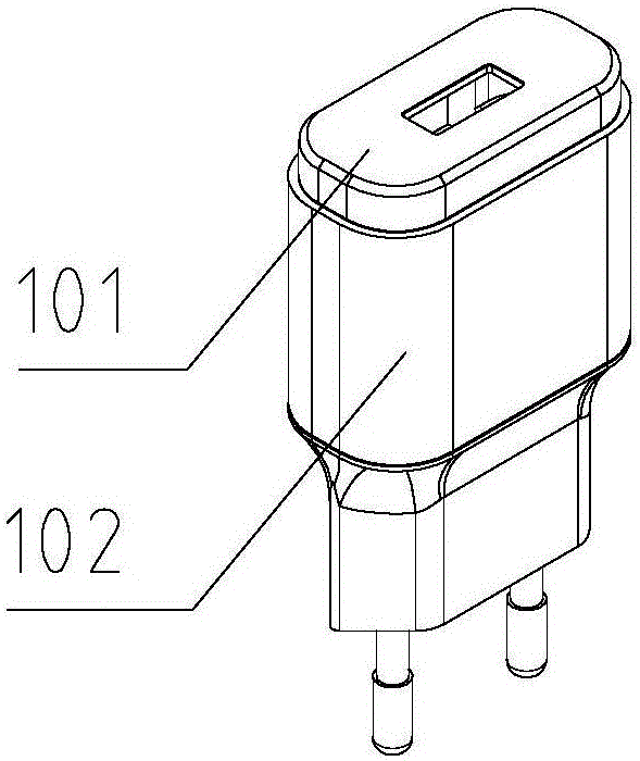
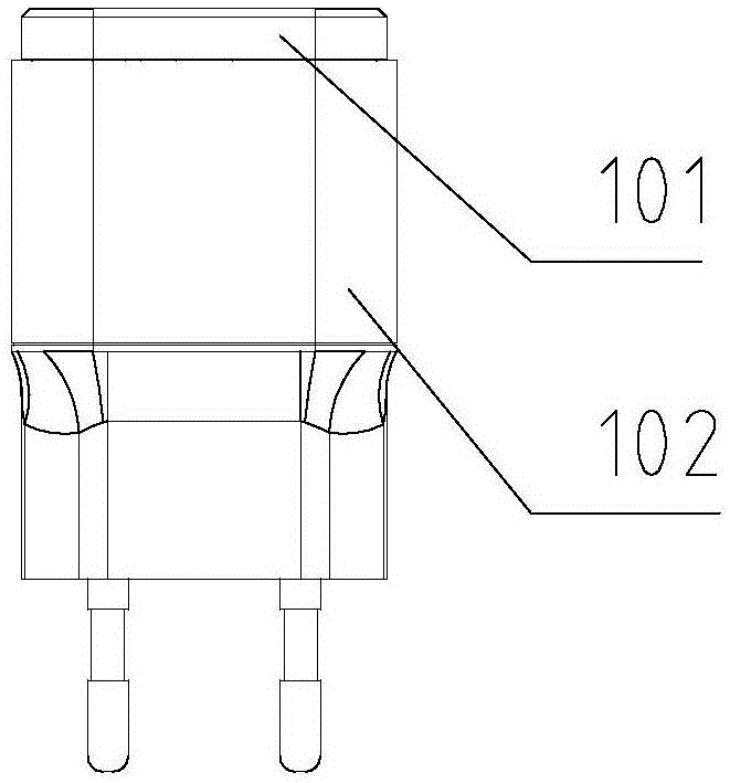
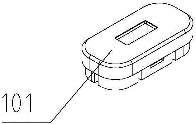
[0043] Such as Figure 1-Figure 17 Shown, be embodiment 1 of the present invention, be provided with vibrating feeding machine 9, be provided with front and rear feeding cylinder 8 on the vibrating feeding machine 9, be provided with vibrating conveying linear guide 7 on the front and rear feeding cylinder 8, vibrating conveying linear guide 7 The front end is respectively provided with a left positioning shrapnel 17 and a right positioning shrapnel 18. The upper part of the front end of the vibration conveying linear guide 7 is provided with a lifting and retrieving cylinder 2, and the front end of the lifting and retrieving cylinder 2 is provided with a clamping and retrieving cylinder 3. A clamping block 4 is provided at the front end.

[0044] During work, the charger upper cover shell 101 is placed on the vibrating conveying linear guide rail 7, the vibrating feeder 9 is opened, the vibrating feeder 9 starts to vibrate, and the charger upper cover 101 is vibrated forward ...

Embodiment 2

[0050] Figure 18-23 It is embodiment 2 of the present invention, Figure 18 It can be seen from the figure that a vibrating feeding machine 9 is provided on one side of the vibrating feeding machine 9, and the front and rear feeding cylinders 8 are arranged on the vibrating feeding machine 9, and the front and rear feeding cylinders 8 are provided with a vibrating conveying linear guide rail 7, and the vibrating conveying straight line The front end of the guide rail 7 is respectively provided with a left positioning shrapnel 17 and a right positioning shrapnel 18. The upper part of the front end of the vibration conveying linear guide rail 7 is provided with a lifting and retrieving cylinder 2, and the front 2 ends of the lifting and retrieving cylinder are provided with a clamping and retrieving cylinder 3. The front end of the material cylinder 3 is provided with a clamping block 4 .

[0051] This embodiment mainly solves that when a set of vibrating feeder 9 cannot meet ...


PUM


Abstract

An automatic feeding device for an upper cover shell of a charger solves the technical problems that an existing manual production and manufacture method for the charger is low in production efficiency, instable in product quality, poor in product consistency, large in worker labor intensity and not capable of achieving automatic batched production. The automatic feeding device is provided with a vibration feeder. A front-back feeding cylinder is arranged on the vibration feeder. Vibration conveying linear guide rails are arranged on the front-back feeding cylinder. A left positioning elastic piece and a right positioning elastic piece are arranged at the front ends of the vibration conveying linear guide rails correspondingly. A lifting material taking cylinder is arranged on the upper portions of the front ends of the vibration conveying linear guide rails. A clamping material taking cylinder is arranged at the front end of the lifting material taking cylinder. Clamping blocks are arranged at the front end of the clamping material taking cylinder. The automatic feeding device can be widely applied to the field of charger manufacturing.

Description

technical field [0001] The invention relates to an automatic device, in particular to an automatic charging device for an upper cover shell of a charger. Background technique [0002] With the rapid development of electronic equipment, the demand for chargers for electronic equipment is also increasing, especially for mobile phone chargers. The cover shell and the internal PCB board are composed. During mass production, the factory relies on the workers on the production line to manually insert the PCB board into the lower shell of the charger, and then manually press the upper cover shell of the charger into the lower shell of the charger. , and finally the preliminarily assembled chargers are welded together by ultrasonic welding to form a complete finished product. [0003] In order to protect the top cover of the charger from scratches, bruises and other quality problems during the assembly process and when it is assembled into a finished product, a layer of the top cov...

Claims


Application Information

Patent Timeline
Patent Type & Authority Applications(China)
IPC IPC(8): B65G47/90B65G27/16
CPCB65G27/16B65G47/90
Inventor 王欢蒲鹏尤建强谭建政唐晓刚徐志伟王会政
Owner 威海志航机电科技有限公司
Why Eureka
Try Eureka