Plastic circular weaving machine

A technology of circular looms and plastics, applied in circular looms, looms, textiles, etc., can solve problems such as time-consuming and labor-intensive, unfavorable product promotion and sales, and increased use costs

Active Publication Date: 2017-03-15
陈耀武
View PDF11 Cites 6 Cited by
  • Summary
  • Abstract
  • Description
  • Claims
  • Application Information

AI Technical Summary

Problems solved by technology

[0002] In the existing plastic circular loom, rollers or rollers are set between the upper door ring and the lower door ring to form a rolling track for the shuttle to run. The rollers or rollers are positioned axially and support the upper and lower door rings to ensure the distance between the upper and lower door rings. When the damaged rollers or rollers need to be replaced, the upper and lower door rings need to be enlarged. Only the distance between the door rings can remove the rotating shaft, and then the rollers and rollers can be replaced, especially when a small number of rollers or rollers need to be replaced, it is also necessary to disassemble all the rotating shafts from the upper door ring to lift the upper door ring, which is time-consuming It is laborious, resulting in a greatly increased cost of use, which is not conducive to product promotion and sales

Method used


Image

  • Plastic circular weaving machine
  • Plastic circular weaving machine
  • Plastic circular weaving machine

Examples


Embodiment 1

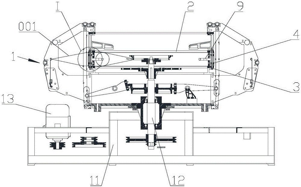
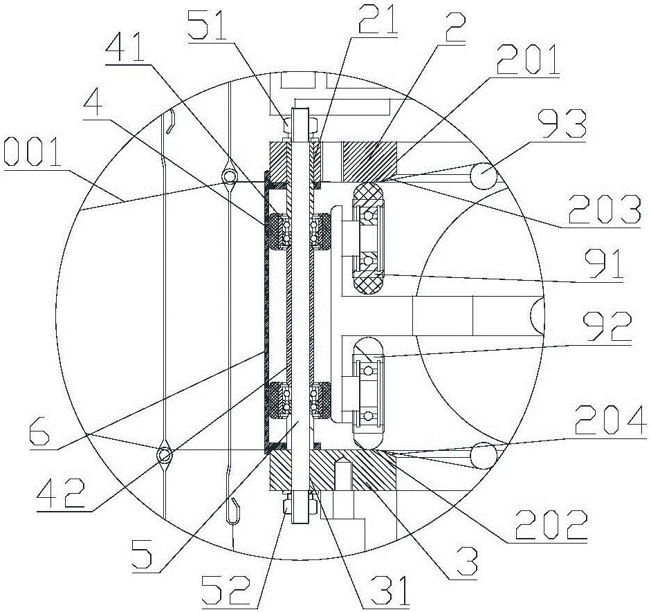
[0025] Such as figure 1 and figure 2 As shown, the present invention provides a kind of plastic circular loom, comprises main frame 1, and main frame 1 comprises frame 11, main shaft 12, door ring assembly and shuttle 9, is provided with motor 13 on frame 11, and main shaft 12 is driven by motor 13, The door ring assembly is installed on the frame 11, and the shuttle 9 is installed on the main shaft 12. The door ring assembly includes an upper door ring 2 and a lower door ring 3, and a plurality of rollers 4 are arranged between the upper door ring 2 and the lower door ring 3, and the rollers 4 The wheel shaft 5 is connected with the door ring assembly, and the roller 4 is distributed along the circumferential direction of the door ring assembly and forms a rolling track for the shuttle 9 to run. The shuttle 9 is provided with an upper limit wheel 91 and a lower limit wheel 92, and the lower surface of the upper door ring 2 There is an upper track surface 201 for the upper l...

Embodiment 2

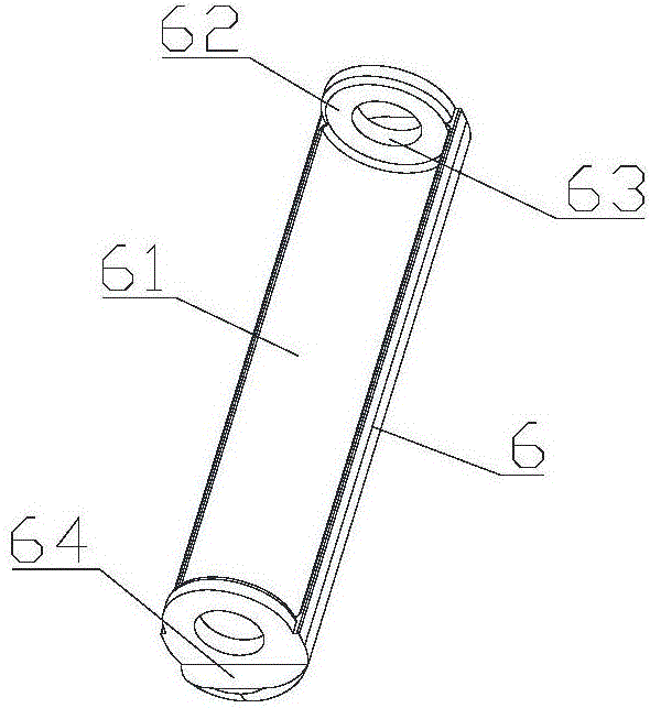
[0034] In this embodiment, the accommodation groove 61 has been improved, that is, how many rollers 4 are on a wheel shaft 5, and how many accommodation grooves 61 are set on a support member 6 correspondingly, as Figure 5 , Figure 6 and Figure 7 As shown, corresponding to the two rollers, one supporting member 6 is provided with two receiving grooves 61 correspondingly, and the receiving grooves 61 are connected through the matching groove 65, the depth of the matching groove 65 is smaller than the depth of the receiving groove 61, and the matching groove 65 An arc-shaped boss 66 is provided, and the arc-shaped boss 66 is to cooperate with the axle sleeve 42 on the wheel shaft 5 to limit the position of the axle sleeve 42. Since the wheel shaft 5 and the axle sleeve 42 will not move during the operation of the shuttle 9 Rotate, so the middle part of the support member 6 cooperates with the shaft sleeve 42, which can improve the supporting effect.

[0035] The content not...

Embodiment 3

[0037] In addition to connecting the top of the wheel shaft 5 with the upper door ring 2 and the bottom end with the lower door ring 3, the wheel shaft 5 can also be divided into two parts, such as Figure 8 As shown, the wheel shaft 5 includes an upper wheel shaft 501 connected with the upper door ring 2 and a lower wheel shaft 502 connected with the lower door ring 3, the bottom end of the upper wheel shaft 501 is suspended, and a roller 4 is arranged on the upper wheel shaft 501, and the top of the lower wheel shaft 502 Suspended, a roller 4 is provided on the lower axle 502 . The number of rollers on the upper wheel shaft 501 and the lower wheel shaft 502 can be increased as required. Since each roller can be removed individually, the rollers 4 can be replaced quickly and in a more targeted manner.

[0038] For the content not described in this embodiment, reference may be made to Embodiment 1 and Embodiment 2.


PUM


Abstract

The invention discloses a plastic circular weaving machine and belongs to the field of plastic weaving machines. The problem that rollers are inconvenient to change in the prior art is solved. According to the technical scheme for solving the problem, the plastic circular weaving machine mainly comprises a mainframe, wherein the mainframe comprises a door ring assembly and a shuttle, the door ring assembly comprises an upper door ring and a lower door ring, multiple rollers are arranged between the upper door ring and the lower door ring and are connected with the door ring assembly through axles, the rollers are distributed in the peripheral direction of the door ring assembly and form a rolling track for the shuttle to operate, the shuttle is provided with an upper limiting wheel and a lower limiting wheel, the lower surface of the upper door ring is provided with an upper track surface for the upper limiting wheel to roll, the upper surface of the lower door ring is provided with a lower track surface for the lower limiting wheel to roll, a supporting part for retaining the separation distance between the upper door ring and the lower door ring is arranged between the upper door ring and the lower door ring, and supporting parts are located on the outer sides of the rollers to protect the rollers in the radial direction of the door ring assembly. The plastic circular weaving machine is mainly used for weaving plastic woven bags.

Description

technical field [0001] The invention relates to a plastic weaving machine, in particular to a plastic circular loom. Background technique [0002] In the existing plastic circular loom, rollers or rollers are set between the upper door ring and the lower door ring to form a rolling track for the shuttle to run. The rollers or rollers are positioned axially and support the upper and lower door rings to ensure the distance between the upper and lower door rings. When the damaged rollers or rollers need to be replaced, the upper and lower door rings need to be enlarged. Only the distance between the door rings can remove the rotating shaft, and then the rollers and rollers can be replaced, especially when a small number of rollers or rollers need to be replaced, it is also necessary to disassemble all the rotating shafts from the upper door ring to lift the upper door ring, which is time-consuming Laborious, resulting in greatly increased cost of use, is not conducive to produ...

Claims


Application Information

Patent Timeline
Patent Type & Authority Applications(China)
IPC IPC(8): D03D37/00
CPCD03D37/00
Inventor 陈耀武
Owner 陈耀武
Why Eureka
Try Eureka