Building suspended ceiling installation structure and construction method thereof
A technology for installing structures and ceilings, applied in building components, building structures, buildings, etc., can solve problems such as complex structures, and achieve the effects of simple installation process, stable connection, and convenient installation.
- Summary
- Abstract
- Description
- Claims
- Application Information
AI Technical Summary
Problems solved by technology
Method used
Image
Examples
Embodiment 1
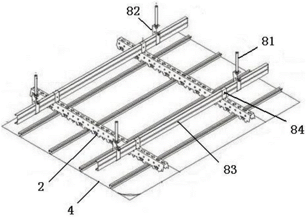
[0067] Such as figure 2 , 4 As shown, the building ceiling installation structure described in this embodiment includes several snap-tooth keels 2 connected to the ceiling 1 through wall connectors 3. The snap-tooth keels 2 are composed of a top surface and two front and rear sides. A connecting hole 21 that matches the wall connector 3 is provided on the top surface of the snap-tooth keel 2, and a slot 22 is arranged at intervals at the bottom of the side of the snap-tooth keel 2, and a buckle is snapped on the snap-tooth keel 22. Plate 4, characterized in that:
[0068] Such as image 3 As shown, upper flanges 41 are provided on both sides of the gusset plate 4, and the top of the upper flange 41 has a snap-in portion 42 that can be snapped into the card slot 22, and the snap-in portions of two adjacent gusset plates 4 42 is snapped into the same slot 22 in a mirror image; it should be noted that: the snap-tooth keel 2 and the pinch plate 4 can also be other matching str...
Embodiment 2
[0092] This embodiment describes the construction method of the building ceiling installation structure described in Embodiment 1, which includes the steps of installing the snap-tooth keel 2 on the ceiling 1 and the step of clamping the buckle plate 4 on the snap-tooth keel 2, which It is characterized in that the step of installing the bayonet keel 2 on the ceiling 1 includes the following steps:
[0093] Drill some rows of mounting holes 11 on the ceiling 1;
[0094] Install the wall connector 3 in the installation hole 11: insert the core rod 6 into the expansion tube 5, and knock the expansion tube 5 into the
[0095] In each installation hole 11, twist the threaded ring 63 to expand the expansion foot 53, securely fix the expansion tube 5 and the core rod 6 on the ceiling 1, and then insert the lifting insertion tube 70 of the lifting assembly 7 into the core rod 6 In the first cylindrical cavity 64, the beads 707 are located in the arc groove 66 when inserted; (in this...
Embodiment 3
[0109] Such as Figure 13 As shown, the building ceiling installation structure described in this embodiment is different from Embodiment 1 in that straight wall sections 56 are provided on both sides of the lower part of the lower pipe body 52 .
[0110] The straight wall sections 56 on both sides are convenient for the vise to clamp the lower pipe body 52 , and the straight wall sections 56 at least partly expose the bottom surface of the ceiling 1 during installation.
PUM
 Abstract
Description
Claims
Application Information
 - R&D
- Intellectual Property
- Life Sciences
- Materials
- Tech Scout
- Unparalleled Data Quality
- Higher Quality Content
- 60% Fewer Hallucinations
Browse by: Latest US Patents, China's latest patents, Technical Efficacy Thesaurus, Application Domain, Technology Topic, Popular Technical Reports.
© 2025 PatSnap. All rights reserved.Legal|Privacy policy|Modern Slavery Act Transparency Statement|Sitemap|About US| Contact US: help@patsnap.com


