
Electronic control hydraulic automatic setting bridge plug device

An electronically controlled hydraulic and hydraulic setting technology, which is applied in sealing/packing, wellbore/well components, earthwork drilling and production, etc., can solve the problem that the well entry tool is easy to be stuck and cannot be lifted out, and cannot meet the on-site safety production and quality requirements, Long time to lose hands and other issues, to achieve the effect of meeting safety production and quality requirements, convenient operation, and reasonable structure

Active Publication Date: 2017-03-15
BC P INC CHINA NAT PETROLEUM CORP +1
View PDF11 Cites 2 Cited by
  • Summary
  • Abstract
  • Description
  • Claims
  • Application Information

AI Technical Summary

Problems solved by technology

[0006] The present invention provides an electronically controlled hydraulic automatic setting bridge plug device, which overcomes the above-mentioned deficiencies in the prior art, and can effectively solve the problem of existing electrohydraulic bridge plugs. The setting device has the problem of being out of hand for a long time, which makes the drilling tool easy to be stuck and unable to be raised, which can no longer meet the safety production and quality requirements of the site

Method used


Image

  • Electronic control hydraulic automatic setting bridge plug device
  • Electronic control hydraulic automatic setting bridge plug device

Examples


Embodiment Construction

[0019] The present invention is not limited by the following examples, and specific implementation methods can be determined according to the technical solutions of the present invention and actual conditions.

[0020] In the present invention, for the convenience of description, the description of the relative positional relationship of each component is based on the description attached to the description. figure 1 For example, the positional relationship of front, back, up, down, left, right, etc. is based on the attached figure 1 determined by the layout direction.

[0021] Below in conjunction with embodiment and accompanying drawing, the present invention will be further described:

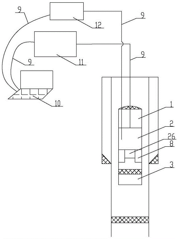
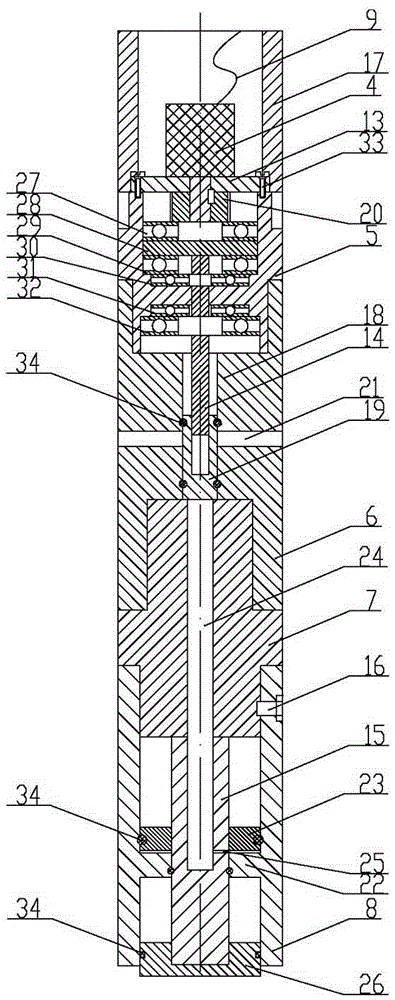
[0022] as attached figure 1 As shown, the electronically controlled hydraulic automatic setting bridge plug device includes a control device, a joint positioner 1, a bridge plug hydraulic setting device 2 and a bridge plug 3; a joint positioner 1, a bridge plug hydraulic setting device 2 a...


PUM


Abstract

The invention provides an electronic control hydraulic automatic setting bridge plug device. The electronic control hydraulic automatic setting bridge plug device comprises a control device, a collar locator, a bridge plug hydraulic setting device and a bridge plug, wherein the collar locator, the bridge plug hydraulic setting device and the bridge plug are sequentially fixed and mounted together from top to bottom; the bridge plug hydraulic setting device comprises a driving device, an intermediate joint, a piston sleeve, a connector and a setting drum; and a signal input terminal of the control device and a signal output terminal of the collar locator are electrically connected together by virtue of an electric cable, and the signal input terminal of the control device and a signal input terminal of the driving device of the bridge plug hydraulic setting device are electrically connected together by virtue of an electric cable. The electronic control hydraulic automatic setting bridge plug device is reasonable and compact in structure and easy to use; by virtue of coordinated application of the control device, the collar locator, the bridge plug hydraulic setting device and the bridge plug, the aims of setting and releasing at a preset position by the bridge plug are realized; the electronic control hydraulic automatic setting bridge plug device has the characteristics of safety, reliability, short setting time and convenience in taking out and recycling of the bridge plug; and the operation is facilitated, the working efficiency is improved, and on-site safety production and quality requirements are met.

Description

technical field [0001] The invention relates to the technical field of setting and sealing bridge plug devices, and relates to an electronically controlled hydraulic automatic setting and sealing bridge plug device. Background technique [0002] Because the formation sealing technology of cable setting bridge plug has the characteristics of short construction period, accurate positioning of bridge plug sealing position and low construction cost, it is widely used in the formation sealing technology of major domestic oil fields. After the cable bridge plug setting and sealing process, an electrohydraulic bridge plug setting device is widely used now, but the electrohydraulic bridge plug setting device commonly used now has the following problems in use: [0003] 1. The electro-hydraulic bridge plug setting tool is used, and the hydraulic pump starts to work from the ground to the downhole motor until the bridge plug is set and lost. Generally, the required power-on working ti...

Claims


Application Information

Patent Timeline
Patent Type & Authority Applications(China)
IPC IPC(8): E21B33/126
CPCE21B33/1208E21B33/126
Inventor 谭文波王新河米红学李国亮蔡永辉唐建军张晓亮董志斌
Owner BC P INC CHINA NAT PETROLEUM CORP
Learn More