
Damper pin for turbine blades

A technology of turbine blades and dampers, applied in the field of damper pins, can solve problems such as expensive tool rework

Active Publication Date: 2017-03-15
GENERAL ELECTRIC TECH GMBH
View PDF4 Cites 4 Cited by
  • Summary
  • Abstract
  • Description
  • Claims
  • Application Information

AI Technical Summary

Problems solved by technology

Therefore, if the damper does not perform as expected, potentially expensive tooling rework may be required

Method used


Image

  • Damper pin for turbine blades
  • Damper pin for turbine blades
  • Damper pin for turbine blades

Examples


Embodiment Construction

[0091] Reference will now be made in detail to present embodiments of the invention, one or more examples of which are illustrated in the accompanying drawings. The detailed description uses numerical and letter designations to refer to features in the drawings. Like or analogous symbols are used in the drawings and description to indicate like or similar parts of the present invention. As used herein, the terms "first," "second," and "third" may be used interchangeably to distinguish one element from another, and are not intended to indicate the position or importance of individual elements.

[0092] The terms "upstream" and "downstream" refer to relative directions with respect to fluid flow in a fluid pathway. For example, "upstream" refers to the direction from which fluid flows, and "downstream" refers to the direction to which fluid flows. The term "radially" means a relative direction generally perpendicular to the axial centerline of a particular component, and the t...


PUM


Abstract

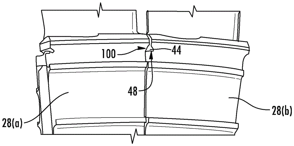
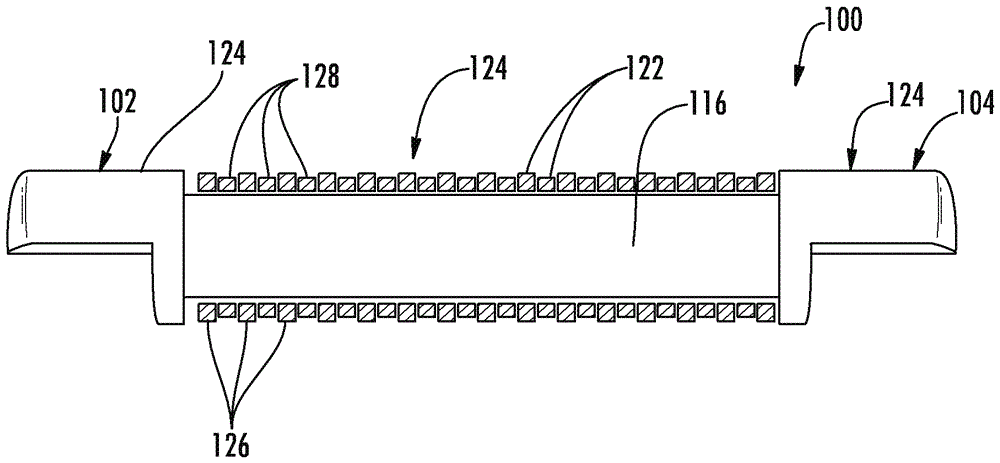
A damper pin (100) for damping adjacent turbine blades (28) coupled to a rotor shaft (22) includes a first end portion (102) that is axially aligned with and axially spaced from a second end portion (104) and a retention pin (116) that is coaxially aligned with and disposed between the first end portion (102) and the second end portion (104). The retention pin (116) couples the first end portion (102) to the second end portion (104). The damper pin (100) further includes a plurality of rings (122) coaxially aligned with and disposed along the retention pin (116) between the first end portion (102) and the second end portion (104). The first end portion (102), the second end portion (104) and the plurality of rings (122) define a generally arcuate outer surface (124) of the damper pin (100) that is configured to contact with a groove defined between the adjacent turbine blades (28).

Description

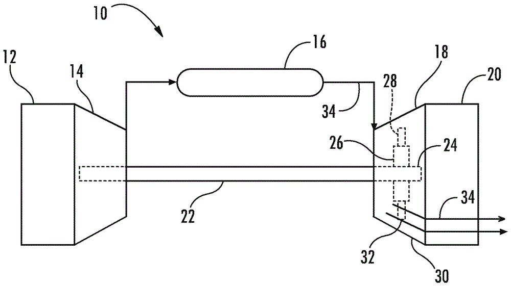
technical field [0001] The present invention generally relates to turbomachines having a plurality of circumferentially aligned turbine blades. More specifically, the present invention relates to a damper pin having a plurality of rings for providing vibration damping between adjacent turbine blades. Background technique [0002] Turbine blades, also known as turbine buckets or turbine rotor blades, convert energy from a flowing fluid, such as hot combustion gases or steam, into mechanical energy by causing the turbine's rotor shaft to rotate. As the turbine transitions through the various modes of operation, the turbine blades experience both mechanical and thermal stress. [0003] Turbine blades generally include an airfoil extending radially outward from a platform, a shank extending radially inward from the platform, and a dovetail or mounting portion extending radially inward from the shank. The dovetail of each turbine blade is secured within a complementary slot def...

Claims


Application Information

Patent Timeline
Patent Type & Authority Applications(China)
IPC IPC(8): F01D5/26
CPCF01D5/26F01D5/22F05D2250/141Y02T50/60F05D2220/32
Inventor S.A.卡雷夫B.D.波特A.C.普雷佩纳贾卡拉
Owner GENERAL ELECTRIC TECH GMBH
Features
  • Generate Ideas
  • Intellectual Property
  • Life Sciences
  • Materials
  • Tech Scout
  • Unparalleled Data Quality
  • Higher Quality Content
  • 60% Fewer Hallucinations
Learn More