Supercharge Your Innovation With Domain-Expert AI Agents!

Superheater expansion tank

An expansion tank and superheater technology, applied in steam superheating, lighting and heating equipment, steam generation, etc., can solve problems such as increased risk, temperature and pressure detection, and increased error rate, so as to improve overall safety and work efficiency. , the effect of quick troubleshooting

Inactive Publication Date: 2017-03-15
扬州市飞马汽油机厂
View PDF0 Cites 3 Cited by
  • Summary
  • Abstract
  • Description
  • Claims
  • Application Information

AI Technical Summary

Problems solved by technology

[0002] As we all know, a superheater is a heating surface in a boiler that heats saturated steam under a certain pressure into superheated steam under a corresponding pressure, which plays an important role in the overall boiler, so the superheater has been widely promoted and applied; the existing The superheater includes an inlet header, an outlet header and a connecting coil, and the input and output ends of the connecting coil are respectively connected with the inlet header and the outlet header; In extreme cases, there will be a risk of explosion, so the superheater expansion tank appeared later, which includes a main body, a working chamber is arranged inside the main body, an inlet pipe, an air outlet pipe and a pressure relief pipe are arranged on the side wall of the main body, and the The air pipe, air outlet pipe and pressure relief pipe are all connected to the working chamber, and a pressure relief valve is installed on the pressure relief pipe; it is found that the expansion tank of this superheater cannot detect the temperature and pressure in the working chamber, so it cannot It can be adjusted to increase the overall risk, and it can only perform manual pressure relief through the pressure relief valve. In extreme cases, the error rate will increase and the risk will increase; it cannot observe the working chamber during work, resulting in its Inability to quickly troubleshoot and overhaul

Method used


Image

  • Superheater expansion tank

Examples


Embodiment Construction

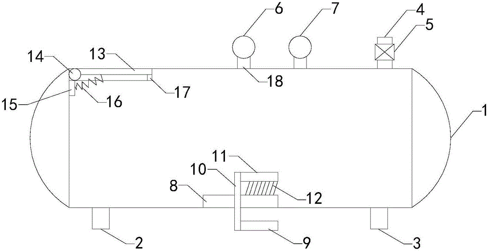
[0009] The specific implementation manners of the present invention will be further described in detail below in conjunction with the accompanying drawings and embodiments. The following examples are used to illustrate the present invention, but are not intended to limit the scope of the present invention.

[0010] Such as figure 1 As shown, the superheater expansion tank of the present invention includes a main body 1, a working chamber is arranged inside the main body, an air inlet pipe 2, an air outlet pipe 3 and a pressure relief pipe 4 are arranged on the side wall of the main body, and the air inlet pipe, the air outlet pipe and the pressure relief pipe 4 are arranged on the side wall of the main body. The pressure pipes are all communicated with the working chamber, and the pressure relief pipe is provided with a pressure relief valve 5; the working chamber is provided with a temperature sensor and a pressure sensor, and the top of the main body is provided with a therm...


PUM


Abstract

The invention relates to the technical field of devices of relieving pressure on superheaters, in particular to a superheater expansion tank. The superheater expansion tank has a pressure and temperature detection displaying function, can automatically relief the pressure to reduce the risk, and furthermore, can be observed to enhance troubleshooting and maintenance effects. The superheater expansion tank comprises a main body, wherein a working cavity is formed in the main body; an air intake pipe, an air outlet pipe and a pressure relief pipe are arranged on the side wall of the main body; a pressure relief valve is arranged on the pressure relief pipe; a temperature sensor and a pressure sensor are arranged in the working cavity; a temperature gauge and a pressure gauge are arranged at the top end of the main body; an observation opening is formed in the bottom wall of the main body; a transparent baffle is arranged at the observation opening; the superheater expansion tank further comprises a handle, a rotating shaft, a drive rod and brush bristles; an air exhaust opening is formed in the top end of the main body, and a stop cover is arranged at the air exhaust opening; the rotating shaft is arranged at the air exhaust opening; a connection block is arranged on the inner wall of the working cavity; and the superheater expansion tank further comprises a double-torsion spring.

Description

technical field [0001] The invention relates to the technical field of devices for relieving the pressure of a superheater, in particular to an expansion tank of a superheater. Background technique [0002] As we all know, a superheater is a heating surface in a boiler that heats saturated steam under a certain pressure into superheated steam under a corresponding pressure, which plays an important role in the overall boiler, so the superheater has been widely promoted and applied; the existing The superheater includes an inlet header, an outlet header and a connecting coil, and the input and output ends of the connecting coil are respectively connected with the inlet header and the outlet header; In extreme cases, there will be a risk of explosion, so the superheater expansion tank appeared later, which includes a main body, a working chamber is arranged inside the main body, an inlet pipe, an air outlet pipe and a pressure relief pipe are arranged on the side wall of the m...

Claims


Application Information

Patent Timeline
Patent Type & Authority Applications(China)
IPC IPC(8): F22G3/00
CPCF22G3/008
Inventor 朱德军
Owner 扬州市飞马汽油机厂
Features
  • R&D
  • Intellectual Property
  • Life Sciences
  • Materials
  • Tech Scout
  • Unparalleled Data Quality
  • Higher Quality Content
  • 60% Fewer Hallucinations
Learn More