
The impact test device and method of the falling mechanism of the front subframe of the automobile

A technology of front subframe and impact test, which is applied in the direction of vehicle impact test, machine/structural component test, impact test, etc. It can solve the problems of inconvenient operation and inability to truly and effectively simulate the working conditions of automobiles, so as to achieve convenient operation, The effect of reliable structure and convenient operation

Active Publication Date: 2019-01-01
CHERY AUTOMOBILE CO LTD
View PDF5 Cites 0 Cited by
  • Summary
  • Abstract
  • Description
  • Claims
  • Application Information

AI Technical Summary

Problems solved by technology

[0003] The prior art most related to the present invention is the patent with the notification number CN201310589575.7 and the title of the invention is "A Mounting Fixture and Its Simulation Test Method for Simulating the Sub-frame Drop-off Test of Automobile", and the disadvantages of this technical solution The disadvantage is that it is inconvenient to operate, and it cannot truly and effectively simulate the working conditions of the front collision of the car
At present, the impact test device that can truly and effectively simulate the mechanism of the car's front sub-frame falling off is still blank

Method used


Image

  • The impact test device and method of the falling mechanism of the front subframe of the automobile
  • The impact test device and method of the falling mechanism of the front subframe of the automobile
  • The impact test device and method of the falling mechanism of the front subframe of the automobile

Examples


Embodiment Construction

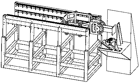
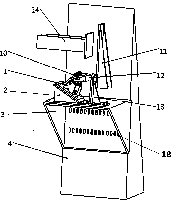
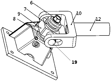
[0033] like figure 1 As shown, the impact test device of the present invention consists of two parts: a clamp device and a driving device. like Figure 5 , figure 2 As shown, the driving device has an impact head 14 , and the clamping device is provided with an impact block 11 matched with the impact head 14 . like figure 2 , image 3 As shown, the outer side of the front sub-frame sample 1 is provided with a shaft sleeve 8 and a pull-off device body 9, such as Figure 4 As shown, the inside of the front sub-frame sample is provided with a fixing nut 5, and the fixing nut 5 is a projection welding nut. like figure 2 , image 3 As shown, the long bolt 6 passes through the pull-off device body 9, the axle sleeve 8, and is fixed with the fixing nut 5 in turn; when the long bolt 6 is connected with the fixing nut 5, it passes through the bolt hole 20 on the front sub-frame sample, as shown in FIG. Image 6 The bolt holes are notched as shown. A certain twist is applied...


PUM


Abstract

The invention relates to an impact testing device and an impact testing method of an automobile front subframe shedding mechanism. The impact testing device is provided with an impact head driven by an impact test driving device and an impact block cooperated with the impact head. An inner side of a front subframe sample piece is provided with a fixing nut, and a long bolt is fixedly connected with the fixing nut after sequentially passes through a pull-out device body and a shaft sleeve. The pull-out device body is provided with a pull-out pin, which horizontally passes through the pull-out device body, and the two ends of the pull-out pin are in a hinged connection with a pull-out fork. Based on a CAE simulation analysis result of a front subframe offset impact working condition, a force application angle and force application magnitude are acquired. The front subframe sample piece is fixedly disposed on a testing angle base, and the inclined angle of the inclined surface of the testing angle base is the same as the force application angle required by the test. By adjusting the output energy of the impact test driving device, the initial kinetic energy of the impact head is greater than the minimum energy required by pull-out motion of a testing sample piece. Under the action of the impact of the impact head, the impact block is used to drive the pull-out fork to act, and then the pull-out fork is used to carry out the pull-out motion by the long bolt under the driving of the pull-out pin.

Description

technical field [0001] The invention relates to an impact test device and method for a falling off mechanism of a front auxiliary frame of an automobile. Background technique [0002] In the prior art, gaps are provided in the bolt holes at the installation points of the front sub-frame and the body bracket, and the connecting bolts between the front sub-frame and the body bracket can fall off through the gap under certain stress conditions, so that when the front collision of the car occurs, , The front sub-frame can be detached from the body, driving the powertrain system connected to it to sink, thereby increasing the crushing space of the front longitudinal beam during the front collision of the car and improving the safety of the car. [0003] The prior art most related to the present invention is the patent with the notification number CN201310589575.7 and the title of the invention is "A Mounting Fixture and Its Simulation Test Method for Simulating the Sub-frame Drop...

Claims


Application Information

Patent Timeline
Patent Type & Authority Patents(China)
IPC IPC(8): G01M7/08G01M17/007
CPCG01M7/08G01M17/0078
Inventor 张迎军徐立笑
Owner CHERY AUTOMOBILE CO LTD
Learn More