fingerprint reader

A technology of fingerprint reader and recognizer, which is applied in the field of electronic recognizers, can solve problems affecting work progress, affecting fingerprint admission, and bad attitude of staff, so as to achieve high work efficiency and accuracy, reduce waiting time, and improve work atmosphere effect

Active Publication Date: 2019-07-19
东莞精旺电子有限公司
View PDF10 Cites 1 Cited by
  • Summary
  • Abstract
  • Description
  • Claims
  • Application Information

AI Technical Summary

Problems solved by technology

[0002] With the advancement of science and technology, people are developing more and more accurate encryption systems. At present, relatively high-end encryption systems include iris scanning, bioelectric scanning, fingerprint scanning, etc. Currently, fingerprint scanning is more commonly used by the public and at a lower cost. , so fingerprint scanning is gradually promoted in all walks of life, and even the national security department will use fingerprint recognition to manage personal information; for example, when applying for personal documents at the police station, fingerprints need to be taken; when taking fingerprints, the applicant's fingers need to be close The touchpad is kept on for 5-10 seconds. The touchpad of the traditional fingerprint reader is horizontal and flat. When placing the finger, the user needs to keep twisting the wrist and pressing the touchpad. During this process, the hand is more sore and the hand shakes It will affect the admission of fingerprints; therefore, in the fingerprint enrollment process, the one-time success rate of fingerprint enrollment in this way is not high; especially when enrolling children's fingerprints, children are naturally active, which greatly affects the work progress and delays other waiters If the waiters and staff are disturbed many times when taking fingerprints, they will feel irritable. This irritability will infect the entire studio, which will make the staff's attitude bad and affect the service attitude. One of the reasons for the bad attitude of the department

Method used


Image

  • fingerprint reader
  • fingerprint reader
  • fingerprint reader

Examples


Embodiment

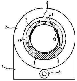
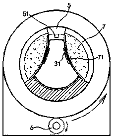
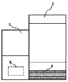
[0017] in Figure 1 to Figure 3 In the illustrated embodiment, the fingerprint reader includes a base 1, on which a drive ring 2 is installed. Inside the drive ring 2, a coaxial sleeve is provided with an elastic touch tube 3, the elastic touch tube 3 Made of transparent skin-friendly materials, skin-friendly materials can improve the touch and reduce the chance of children twisting their fingers, thereby increasing the efficiency of fingerprint enrollment; the drive ring 2 can rotate freely around its own axis relative to the elastic touch tube 3;

[0018] An identifier 4 and a locator 5 are fixedly installed between the drive ring 2 and the elastic touch cylinder 3 on the inner ring surface of the drive ring 2. The line between the center of the locator 5 and the identifier 4 and the axis of the drive ring 2 Intersect; the recognizer 4 is in the shape of a circular arc, the recognition surface of the recognizer 4 is directly opposite to the elastic touch tube 3; the locator 5 i...


PUM


Abstract

The invention relates to a fingerprint identifier. The fingerprint identifier includes a base, on which a drive ring is mounted, and inside the drive ring, an elastic touch cylinder is coaxially sleeved; the drive ring can be positioned relative to the elastic touch cylinder. , freely rotate around its own axis; between the drive ring and the elastic touch cylinder, a recognizer and a locator are fixedly installed on the inner ring surface of the drive ring, and the connecting line between the center of the locator and the recognizer is connected to the axis of the drive ring intersect; the recognizer is in the shape of an arc sheet, and the recognition surface of the recognizer is facing the elastic touch cylinder; the locator includes an infrared detection head, and the infrared detection head is facing the elastic touch cylinder; the drive The ring is electrically rotated by a drive motor, and the drive motor, the recognizer and the locator are respectively electrically connected to the computer chip; the fingerprint recognizer has a delicate structure and can dynamically and efficiently align finger fingerprints to improve the success rate of fingerprint registration.

Description

Technical field [0001] The invention relates to an electronic identifier, in particular, a fingerprint identifier. Background technique [0002] With the advancement of science and technology, people are becoming more and more precise in the development of encryption systems. At present, the relatively high-end encryption systems include iris scanning, bioelectric scanning, fingerprint scanning, etc. At present, fingerprint scanning is more commonly used by the public and at the same time the cost is more affordable. Therefore, fingerprint scanning is gradually promoted in all walks of life, and even the national security department will use fingerprint identification methods to manage personal information; for example, when applying for personal identification at a police station, fingerprints are required; fingerprints must be closely attached to the applicant’s finger The touchpad is held for 5-10 seconds. The touchpad of the traditional fingerprint reader is a horizontal flat...

Claims


Application Information

Patent Timeline
Patent Type & Authority Patents(China)
IPC IPC(8): G06K9/00
CPCG06V40/13
Inventor 朱虹斐
Owner 东莞精旺电子有限公司
Why Eureka
Try Eureka