
Lens correction method and device

A correction method and technology of a correction device, which are applied in the direction of television, electrical components, image communication, etc., can solve problems such as correction errors, and achieve the effect of avoiding correction errors and improving accuracy.

Active Publication Date: 2018-09-18
ZHEJIANG UNIVIEW TECH CO LTD
View PDF9 Cites 0 Cited by
  • Summary
  • Abstract
  • Description
  • Claims
  • Application Information

AI Technical Summary

Problems solved by technology

[0006] The present invention provides a lens correction method and device to solve the problem of correction error caused by the existence of false clear points in the existing lens correction scheme

Method used


Image

  • Lens correction method and device
  • Lens correction method and device
  • Lens correction method and device

Examples


Embodiment Construction

[0023] In order to enable those skilled in the art to better understand the technical solutions in the embodiments of the present invention, and to make the above-mentioned purposes, features and advantages of the embodiments of the present invention more obvious and understandable, the following describes the technical solutions in the embodiments of the present invention in conjunction with the accompanying drawings Further detailed instructions.

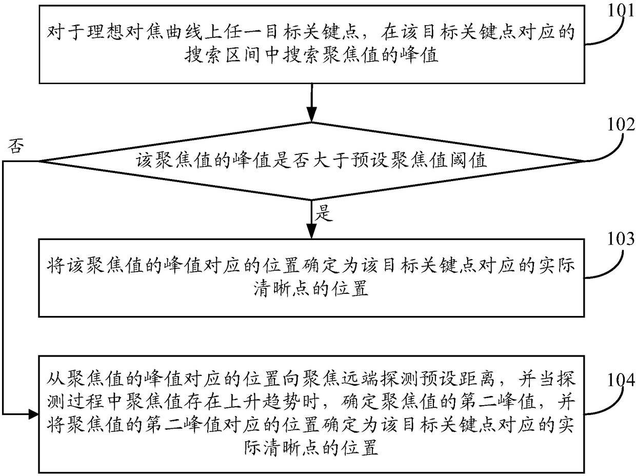
[0024] See figure 1 , figure 1 A schematic flow chart of a lens correction method provided by an embodiment of the present invention, as shown in figure 1 As shown, the lens correction method can include:

[0025] Step 101. For any target key point on the ideal focus curve, search for the peak value of the sharpness evaluation value in the search interval corresponding to the target key point.

[0026] In the embodiment of the present invention, the target key point does not specifically refer to a fixed key point, but may refe...


PUM


Abstract

The invention provides a lens correction method and a lens correction device. The method comprises the steps of searching a peak of definition evaluation values within a search region corresponding to any target key point of an ideal focusing curve; judging whether the peak of the definition evaluation values is more than a preset definition evaluation value threshold; if yes, determining a position corresponding to the peak of the definition evaluation values to be a position of an actual clear point corresponding to the target key point; and otherwise, detecting for a preset distance from the position corresponding to the peak of the definition evaluation values to a focusing remote end, determining a second peak of the definition evaluation values when the definition evaluation values during the detection process has a rising trend, and determining the position corresponding to the second peak of the definition evaluation values to be the position of the actual clear point corresponding to the target key point. By using the method and the device provided by the embodiment of the invention, accuracy of lens correction can be improved.

Description

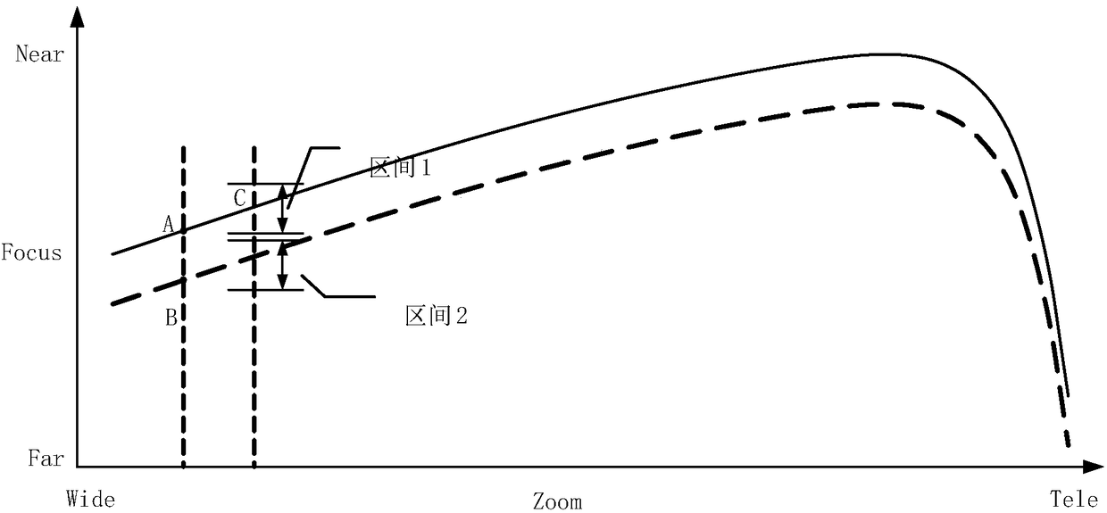
technical field [0001] The invention relates to the technical field of video monitoring, in particular to a lens correction method and device. Background technique [0002] The zoom lens needs to rely on the focus curve of the lens when performing zoom follow and auto focus operations. During the zoom follow process, only the Zoom (zoom) and Focus (focus) motors move along the focus curve to ensure clear images throughout the process. When designing a lens, the lens manufacturer will provide a set of design curves, which is the ideal focus curve. The focus curve is related to the object distance, and the focus curve is different at different object distances. Due to the existence of individual differences in lenses, there is a certain deviation between the actual focus curve of each lens and the ideal focus curve. If the ideal focus curve is used during the lens zoom follow process, there will be varying degrees of blur during the follow process. Therefore, in actual use, ...

Claims


Application Information

Patent Timeline
Patent Type & Authority Patents(China)
IPC IPC(8): H04N17/00
CPCH04N17/002
Inventor 史飞吕乾坤陈天钧陈芳
Owner ZHEJIANG UNIVIEW TECH CO LTD
Learn More