

Uranium mining method by in-situ loosening and leaching
A leaching and in situ technology, applied in the field of uranium mining and smelting, can solve the problems of difficult support, easy collapse and falling blocks, and low efficiency.
Active Publication Date: 2014-07-23
BEIJING RESEARCH INSTITUTE OF CHEMICAL ENGINEERING AND METALLURGY
View PDF0 Cites 13 Cited by
- Summary
- Abstract
- Description
- Claims
- Application Information
AI Technical Summary
Problems solved by technology
(the average pumping volume is less than 0.8-1.2m3 / d), low efficiency and high cost; using conventional underground mining methods, the sandstone layer is relatively loose
Scattered, easy to collapse and drop blocks, difficult to support, and the ore-bearing aquifer layer has a large amount of water supply
There is currently no effective way to develop such mines
Method used
View moreImage
Smart ImageViewing Examples

Examples
Embodiment 1
Embodiment 2
Embodiment 3
Login to View More PUM
| Property | Measurement | Unit |
|---|---|---|
| diameter | aaaaa | aaaaa |
| height | aaaaa | aaaaa |
| diameter | aaaaa | aaaaa |
Abstract
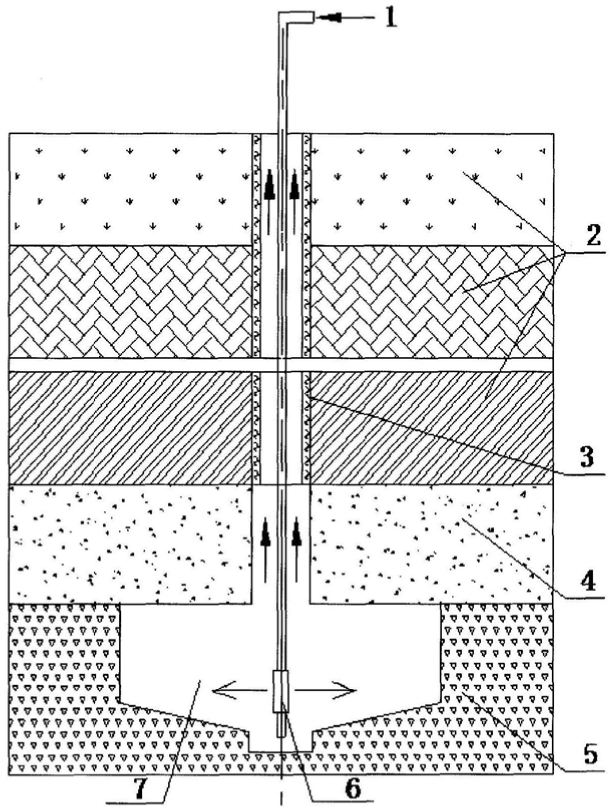
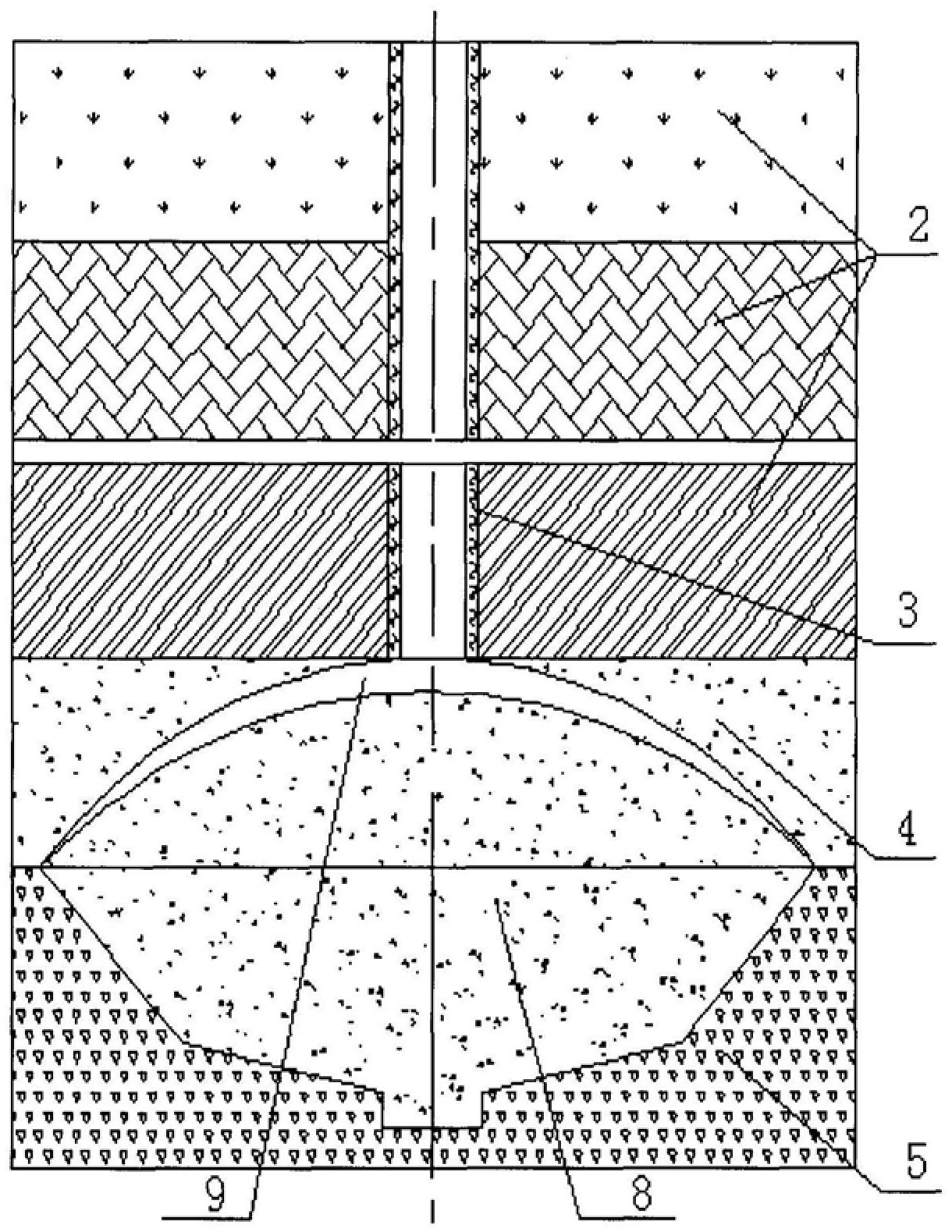
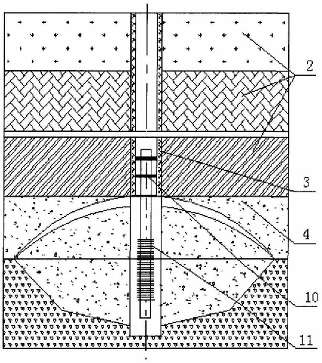
The invention provides a method for mining uranium by in-situ loosening and leaching. The steps are: (a) forming the borehole structure; (b) running the casing from the borehole into the ore-bearing aquifer; (c) running the hydraulic roadhead into the bottom of the borehole along the casing to excavate Form a compensation chamber with a circular plane; (d) adopt the method of blasting, and the caving ore falls into the compensation chamber to form a loose dome; (e) run the plug and the leaching borehole filter into the , forming a liquid pumping borehole; (f) drill 2 to 4 liquid injection boreholes around the liquid pumping borehole, and the bottoms of the liquid injection borehole and the liquid pumping borehole are located at the position of the compensation chamber; (g) from The leaching solution is injected into the liquid injection borehole, and the leaching solution containing useful metal components is extracted from the liquid suction borehole. The invention improves the permeability of the ore, reduces the gluing and mechanical blockage of clay substances in the ore, and maximizes the pumping and injection volume of the ground leaching borehole.
Description
In-situ loosening and leaching uranium mining method Technical field [0001] The present invention relates to the technical field of uranium mining and smelting, in particular to a method for mining uranium by loosening and leaching in situ. Background technique There is a large amount of low-permeability sandstone uranium deposits in my country at present, as Inner Mongolia Ordos Basin sandstone uranium deposits, The amount of uranium resources is nearly 10,000 tons, but the average permeability coefficient of the ore layer is less than 0.165m / d. The average permeability coefficient of the bed is 0.5m / d, and the ore body is in the form of agglomerates and blocks. These deposits are mined by in-situ leaching, and the boreholes pump out less liquid (the average pumping volume is less than 0.8-1.2m3 / d), low efficiency and high cost; using conventional underground mining methods, the sandstone layer is relatively loose Scattered, easy to collapse and drop blocks, difficul...
Claims
Login to View More Application Information
Patent Timeline
 Patent Type & AuthorityPatents(China)
IPC IPC(8): E21B43/10C22B3/02
Inventor胡柏石姜岩牛玉清谭亚辉
OwnerBEIJING RESEARCH INSTITUTE OF CHEMICAL ENGINEERING AND METALLURGY