Laser thruster micro-impulse test device
A technology of testing devices and thrusters, which is applied in the direction of measuring devices, force/torque/power measuring instruments, instruments, etc., to achieve the effects of easy implementation, high test accuracy, and high impulse test accuracy
Active Publication Date: 2007-08-22
PLA PEOPLES LIBERATION ARMY OF CHINA STRATEGIC SUPPORT FORCE AEROSPACE ENG UNIV
View PDF0 Cites 17 Cited by
- Summary
- Abstract
- Description
- Claims
- Application Information
AI Technical Summary
Problems solved by technology
-6
~10
Method used
View moreImage
Smart ImageViewing Examples

Examples
Embodiment Construction
[0031]
[0033]
[0035]
[0036] So
[0037]
[0038]
[0039]
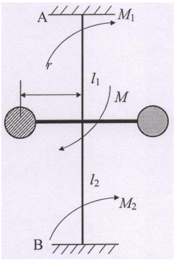
[0040] Wherein, ω is a frequency, T is a period of rotation, and J is a moment of inertia.
[0042]
[0044]
[0046]
[0049]
[0050]
[0052]
[0053] Record T, θmax and r, calculate J according to the torsional pendulum system, and substitute into formula (13) to obtain the impulse of impact force.
Login to View More PUM
 Abstract
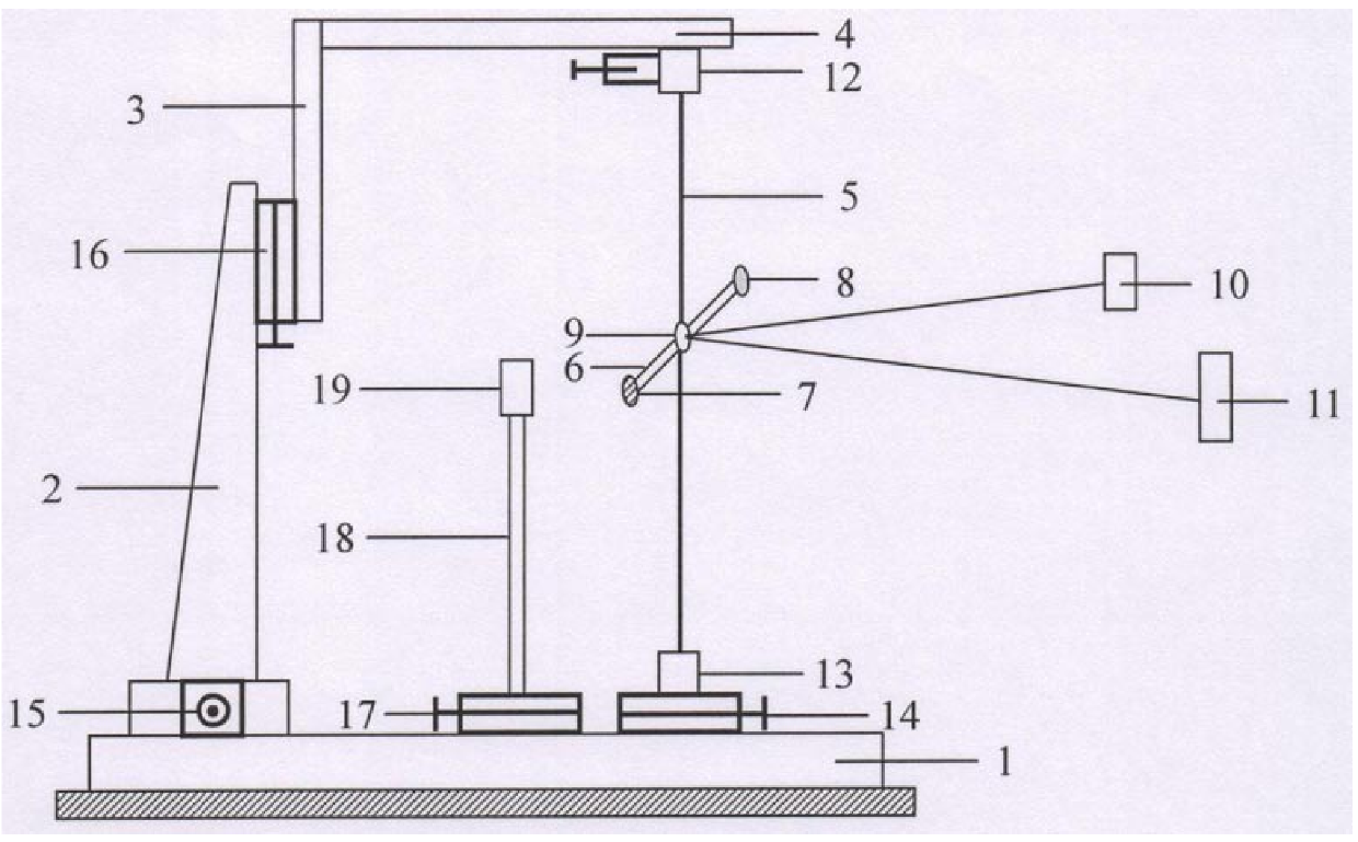
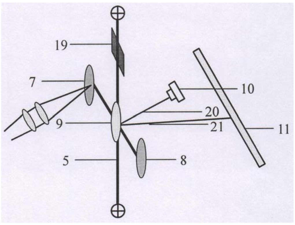
The invention relates to a micro-impulse testing device for a laser thruster. It includes a ㄈ-shaped frame composed of a base plate, a vertical bar and a cross bar. A vertical swing wire is suspended between the base plate and the cross bar of the ㄈ-shaped frame. A beam perpendicular to the swing wire is fixed in the middle of the swing wire. The other end is a counterweight, and the crossbeam at the intersection with the pendulum wire is equipped with a reflector, the laser that irradiates the mirror, and the scale that receives the detection laser beam, and the upper and lower ends of the pendulum wire are fixed by the clamping mechanism. The calculation model of the impact force impulse of the laser thruster micro-impulse test device is given. The advantage is that the measuring range is wide, the testing precision is high, the device is easy to implement, and the parameter calibration method is simple and easy.
Description
Technical field of laser thruster micro-impulse test device The invention belongs to the technical field of space propulsion, in particular to the field of micro-impulse testing technology of a kind of micro-thruster area. Background technique The impulse range of laser plasma micro-thruster is generally at 10 -6 ~10 -4 Between N·s magnitude. micro thruster Micro-impulse measurement is one of the key technologies in the study of micro-propulsion technology. At present, the single-pulse impulse test publicly reported at home and abroad Methods include laser interferometry and torsional pendulum test. Laser interferometry is simple and easy to measure small thrust and single pulse impulse The ideal method, but the laser interferometry uses a laser interferometer, because the laser interferometer is expensive, it is rarely used. therefore The torsional pendulum micro-impulse test method has been more favored. [0003] In 1774, Coulomb invented the Coulomb to...
Claims
Login to View More Application Information
Patent Timeline
 Patent Type & Authority Patents(China)
IPC IPC(8): G01L5/12
Inventor 洪延姬陈景鹏金星王军李修乾李倩姚宏林王广宇叶继飞文明
Owner PLA PEOPLES LIBERATION ARMY OF CHINA STRATEGIC SUPPORT FORCE AEROSPACE ENG UNIV
Features
- R&D
- Intellectual Property
- Life Sciences
- Materials
- Tech Scout
- Unparalleled Data Quality
- Higher Quality Content
- 60% Fewer Hallucinations
Learn More Browse by: Latest US Patents, China's latest patents, Technical Efficacy Thesaurus, Application Domain, Technology Topic, Popular Technical Reports.
© 2025 PatSnap. All rights reserved.Legal|Privacy policy|Modern Slavery Act Transparency Statement|Sitemap|About US| Contact US: help@patsnap.com