Automatic garlic planter

A planter and garlic technology, applied in the direction of single-seed planter, planter parts, etc., can solve the problems of inability to achieve erection of the cusp upwards, failure to meet the requirements of garlic planting, and high labor intensity of staff, and to improve erection and erection. High planting rate, high seeding depth qualification rate and good seeding depth consistency

Inactive Publication Date: 2017-03-22
SHANDONG UNIV OF TECH
0 Cites 8 Cited by

AI-Extracted Technical Summary

Problems solved by technology

[0002] Garlic seeds are irregular in shape and need to be planted upright with a single cusp. Therefore, it is difficult to realize mechanized planting. At present, garlic planting mainly relies on manual labor. Not only the labor intensity of the staff is high, but also the planting efficiency is low, so it is urgent to replace manual Garlic planting machinery for planting
Currently commonly used garlic planters mainly include traction and self-propelled. The traction garlic planter has a simple structure and small dimensions, but mo...

Method used

The present invention is simple in structure, and design is reasonable, can realize that the cusp of garlic upwards is planted upright, does not need people to directly participate in in planting process, has realized the mechanical automa...

Abstract

The invention relates to an automatic garlic planter, and belongs to the technical field of agricultural machinery. A seed box and a seed sowing device are fixed on the upper part of a frame; an outlet of the seed box corresponds to an inlet of the seed sowing device; a seed outlet of the seed sowing device corresponds to an upper orientation hopper; a lower orientation hopper is correspondingly arranged below the upper orientation hopper; an orientation hopper opening device and an orientation hopper opening transmission device are arranged at the rear of the upper orientation hopper and the lower orientation hopper correspondingly; a receiving hopper is correspondingly arranged below the lower orientation hopper; an upright seed sowing rotary plate is fixed below the receiving hopper; an outlet of the receiving hopper corresponds to a duckbill on the upright seed sowing rotary plate; a cam is arranged below the upright seed sowing rotary plate; the frame is connected with land wheels through a land wheel supporting frame; a press wheel is arranged at the rear of the frame; a soil flattening device is arranged below the front of the frame; and a suspension bracket is arranged on the frame. The automatic garlic planter is simple in structure, mechanical automatic garlic planting is realized, the labor intensity of workers is reduced, the orientation effect is good, the upright planting rate is high, and the efficiency of the planter can further be improved.

Application Domain

Seed depositing seeder partsSingle grain seeders

Technology Topic

Agricultural engineeringCam +1

Image

  • Automatic garlic planter
  • Automatic garlic planter
  • Automatic garlic planter

Examples

  • Experimental program(1)

Example Embodiment

[0024] The embodiments of the present invention will be further described below in conjunction with the accompanying drawings:
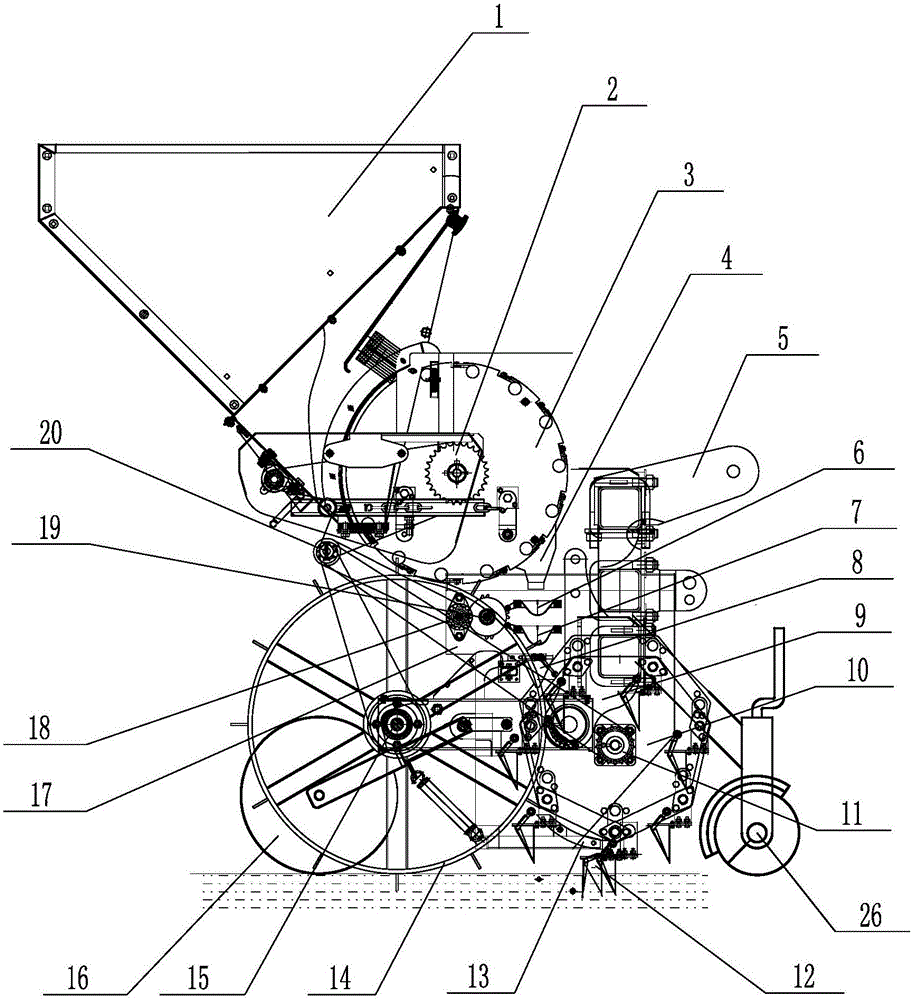
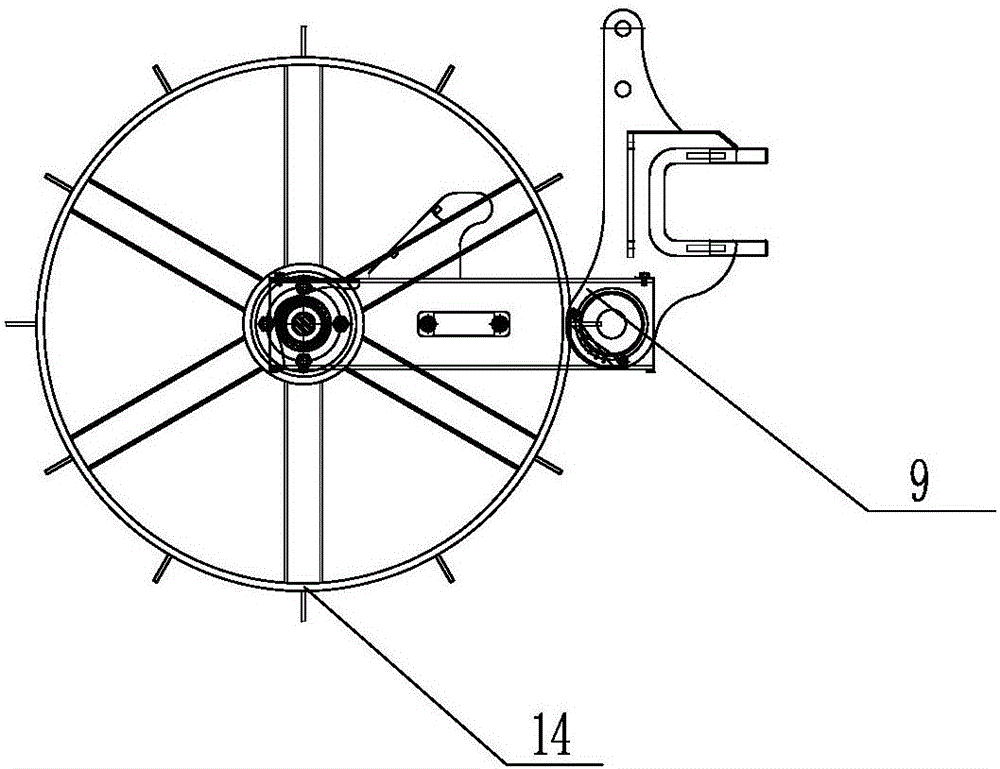
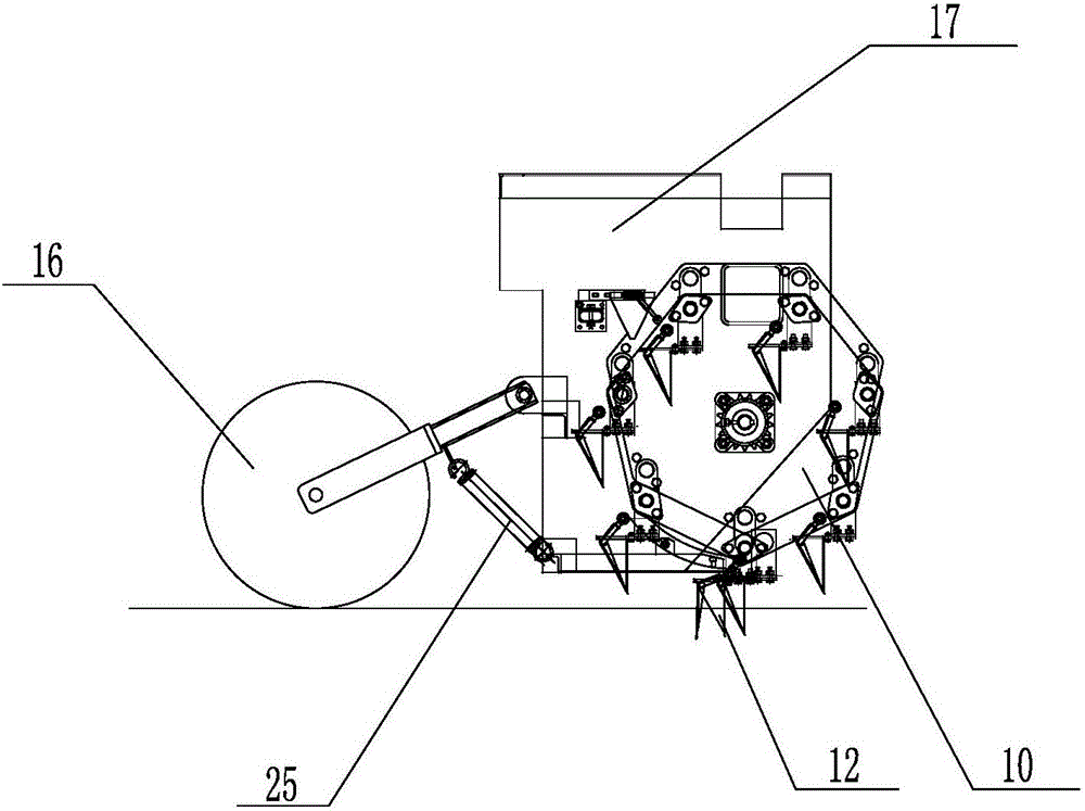
[0025] Such as Figure 1-3 As shown, the automatic garlic planting machine of the present invention includes a frame 17, a seed box 1 and a seed meter 3 are fixed on the upper part of the frame 17, and the outlet of the seed box 1 corresponds to the entrance of the seed meter 3, and is characterized in : The seed metering outlet 4 of the seed metering device 3 corresponds to the upper directional bucket 6 set below the seed metering device 3, and the lower directional bucket 7 is correspondingly set below the upper directional bucket 6, and the corresponding upper directional bucket 6 and the lower directional bucket 7 The directional bucket opening device 19 and the directional bucket opening transmission device 18 are arranged at the rear. The directional bucket opening device 19 is engaged with the directional bucket opening transmission device 18 through gears, and the directional bucket opening transmission device 18 is connected to the intermediate transmission shaft 20 through a sleeve roller chain. , The intermediate drive shaft 20 is respectively connected to the ground wheel shaft 15, the turntable shaft 11 and the seed metering shaft 2 through a sleeve roller chain, a receiving hopper 8 is correspondingly provided under the lower directional hopper 7, and the vertical seeding turntable 10 is fixed below the receiving hopper 8 The outlet of the hopper 8 corresponds to the duckbill 12 set on the direct seeding carousel 10. A plurality of duckbills 12 are arranged on the direct seeding carousel 10 evenly distributed along the circumference, and a duckbill 12 is arranged under the direct seeding carousel 10 The matching duckbill at the opening opens the cam 13, the frame 17 is connected to the ground wheel 14 through the ground wheel support frame 9, the back of the frame 17 is provided with a pinch wheel 16, and a pinch wheel spring 25 is provided between the pinch wheel 16 and the frame 17 , The leveling device 26 is arranged under the front of the frame, and the leveling device is equipped with a height adjustment device relative to the frame. The frame 17 is provided with a suspension frame 5, and the suspension frame 5 includes an upper suspension frame and a lower suspension frame fixed at the front end of the frame 17 Suspension frame.
[0026] The soil leveling device is composed of two screw conveying devices with opposite rotation directions, which are driven and rotated by the power output shaft of the tractor to transport the soil in the middle to both sides. When the machine moves forward, the ground that the soil leveling device passes through is leveled. It is fixed at a suitable position on the frame, and its shaft is connected with the power output shaft of the tractor with a coupling and a transmission shaft.
[0027] Such as Figure 4 As shown, the directional bucket opening device 19 includes an upper directional bucket opening cam 21 and a lower directional bucket opening cam 22. The upper directional bucket opening cam 21 and the lower directional bucket opening cam 22 are respectively associated with the upper directional bucket 6 and the lower directional bucket 7 Corresponding. The upper directional bucket 6 and the lower directional bucket 7 both include a left half directional bucket 23 and a right half directional bucket 24. The left half directional bucket 23 and the right half directional bucket 24 have the same structure and are symmetrically hinged.
[0028] The upper directional bucket opening cam 21 and the lower directional bucket opening cam 22 are coaxially fixed, and the upper directional bucket opening cam 21 and the lower directional bucket opening cam 22 are provided with a plurality of gear teeth. The gear teeth are preferably evenly distributed on the circumference.
[0029] The gear teeth of the upper directional bucket opening cam 21 and the lower directional bucket opening cam 22 are staggered and fixed by 5-20° in sequence.
[0030] The working principle and use process of the present invention:
[0031] When the present invention is in use, the automatic garlic planting machine is connected to the tractor through the suspension frame 5, and an appropriate amount of garlic seeds are placed in the seed box 1. When working, the ground wheel 14 touches the ground, the leveling device 26 touches the ground, the automatic garlic planter is hauled forward by the tractor, the ground wheel 14 rotates, the ground wheel shaft 15 of the ground wheel 14 drives the intermediate drive shaft 20 to move, and then passes through the middle The transmission shaft 20 drives the turntable shaft 11 and the seed metering device shaft 2 to move, that is, drives the vertical seeding turntable 10 and the seed metering device 3 to rotate. The seed meter 3 continuously picks seeds from the seed box 1 during the continuous rotation, and discharges them into the upper directional bucket 6 below the seed outlet 4 through the seed outlet 4, and the garlic seeds stay in the upper directional bucket 6 After 0.1-1 second, the upper directional bucket 6 is opened symmetrically by the upper directional bucket opening cam 21, and the garlic seeds fall into the lower directional bucket 7. After the garlic seeds stay in the lower directional bucket 7 for 0.1-1 second, the lower directional bucket 7 is removed from the bottom The directional bucket opening cam 22 opens symmetrically, and the garlic seeds fall into the receiving hopper 8. The shape of the upper directional bucket 6 and the lower directional bucket 7 orients the garlic seeds twice, so that the garlic seeds fall into the receiving hopper 8 With the tip of the teeth facing upwards, the mouth of the duckbill 12 on the vertical seeding carousel 10 is always upward when it rotates with the standing seeding carousel 10. When the duckbill 12 rotates to just below the receiving hopper 8, the receiving hopper 8 opens and the receiving hopper 8 The garlic seeds fall into the duck's bill 12, and the duck's bill 12 rotates to reach the bottom of the direct seeding turntable 10, enters the soil and opens under the action of the duck bill opening cam 13, and the garlic seeds are planted upright in the soil.
[0032] The invention has simple structure and reasonable design, can realize garlic planting upright with the tooth tip upward, does not require direct participation in the planting process, realizes mechanical automatic planting of garlic, reduces the labor intensity of workers, and can improve the efficiency of the planting machine. By adjusting the orientation twice, it has a better orientation effect and increased the vertical planting rate.
[0033] The present invention is not limited to the above-mentioned specific embodiments, and changes, modifications, additions or substitutions made by persons of ordinary skill in the art within the essential scope of the present should also fall within the scope of protection of the present invention.

PUM

no PUM

Description & Claims & Application Information

We can also present the details of the Description, Claims and Application information to help users get a comprehensive understanding of the technical details of the patent, such as background art, summary of invention, brief description of drawings, description of embodiments, and other original content. On the other hand, users can also determine the specific scope of protection of the technology through the list of claims; as well as understand the changes in the life cycle of the technology with the presentation of the patent timeline. Login to view more.

Similar technology patents

Body condition measuring device

InactiveUS20050234351A1simple structure
Owner:DENSO CORP

Magnetic cooling apparatus and control method thereof

ActiveUS20130180263A1simple structure
Owner:SAMSUNG ELECTRONICS CO LTD

Dual-Drivetrain of Power-Assist Vehicle

InactiveUS20100181130A1enhance uphill momentumsimple structure
Owner:CHOU WEN CHENG

Classification and recommendation of technical efficacy words

  • Simple structure
  • reasonable design

Sharing system for air-conditioning coat

InactiveCN107440179ASimple structureeasy to wear
Owner:QINGDAO HAIER AIR CONDITIONER GENERAL CORP LTD

Feeding device of sorter of batteries plate

InactiveCN101357717ASimple structurecooperate well
Owner:NANJING NORMAL UNIVERSITY

Emergency parachuting device and method for multiple-rotor unmanned aerial vehicle

InactiveCN103895870Aavoid aircraft crashSimple structure
Owner:SOUTH CHINA AGRI UNIV +1

Embedding accuracy control construction method for embedded part of overlong equipment foundation platform

InactiveCN102134879Areasonable designSimple construction steps
Owner:SCEGC NO 6 CONSTR ENG GRP CO LTD
Why Eureka
Try Eureka