Centrifugal chip capable of achieving sequential reactions and mixing method thereof

A sequential reaction and centrifugal technology, applied in the field of microfluidics, can solve the problems of increased operation difficulty, inconvenient integration, difficulty in sample injection and multiple sequential reactions, etc., and achieves the effect of convenient operation, reduced equipment cost, and free time control.

Active Publication Date: 2017-03-22
SUZHOU WENHAO MICROFLUIDIC TECH CO LTD
View PDF6 Cites 19 Cited by
  • Summary
  • Abstract
  • Description
  • Claims
  • Application Information

AI Technical Summary

Problems solved by technology

[0004] For centrifugal chips, it is difficult to realize the injection of more than two samples and multiple sequential reactions
In general, sample injection adopts the method of reagent pre-embedding, and the sequential reaction of fluid is controlled by microvalve. Commonly used microvalves are mainly divided into active microvalve and passive microvalve. Active microvalve has moving parts, which has high reliability, but is not convenient. integrated
Passive microvalve mainly relies on the surface properties of the material, the physical properties of the liquid being operated, and the structure of the microchannel to achieve flow cut-off, but most siphon valves require hydrophilic treatment of the chip, which increases the difficulty of operation

Method used


Image

  • Centrifugal chip capable of achieving sequential reactions and mixing method thereof
  • Centrifugal chip capable of achieving sequential reactions and mixing method thereof
  • Centrifugal chip capable of achieving sequential reactions and mixing method thereof

Examples


Embodiment Construction

[0026] The technical solutions in the embodiments of the present invention will be described in detail below in conjunction with the accompanying drawings in the embodiments of the present invention. Obviously, the described embodiments are only some of the embodiments of the present invention, not all of them. Based on the embodiments of the present invention, all other embodiments obtained by persons of ordinary skill in the art without making creative efforts belong to the protection scope of the present invention.

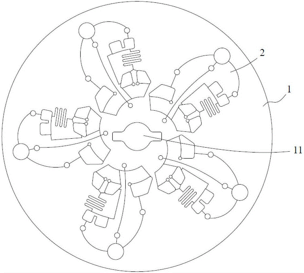
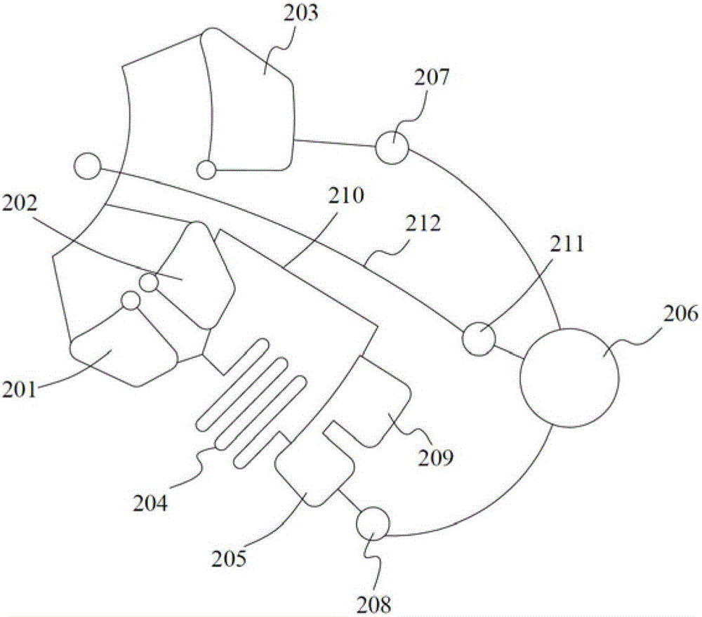
[0027] combine figure 1 and figure 2 As shown, the centrifugal chip capable of sequential reaction includes a chip body 1 and at least one microchannel unit 2 formed on the chip body. The microchannel unit 2 includes a first liquid reservoir 201, a second liquid reservoir 202, The third liquid storage tank 203, mixing channel 204, quantitative tank 205 and detection tank 206, the mixing channel 204, quantitative tank 205 and detection tank 206 are connected i...


PUM


Abstract

This application discloses a centrifugal chip capable of achieving sequential reactions and a mixing method thereof. The chip comprises a chip body, and at least one microchannel unit formed on the chip body, wherein the microchannel unit comprises a first liquid storage tank, a second liquid storage tank, a third liquid storage tank, a mixing channel, a quantitative tank and a detection tank; the mixing channel, the quantitative tank and the detection tank communicated with one another in sequence along a direction far from a centrifugal axis; the first liquid storage tank and the second liquid storage tank communicate with the mixing channel respectively, and are positioned between the mixing channel and the centrifugal axis; the detection tank communicates with the third liquid storage tank; a first micro valve is arranged between the detection tank and the third liquid storage tank; the third liquid storage tank, relative to the detection tank, is closer to the centrifugal axis; and a second micro valve is arranged between the detection tank and the quantitative tank. The centrifugal chip disclosed by the invention can achieve sequential reactions, and is low in cost and convenient in control.

Description

technical field [0001] The application belongs to the field of microfluidic technology, and in particular relates to a centrifugal chip capable of realizing sequential reactions for high-throughput detection and a mixed detection method thereof. Background technique [0002] Microfluidic chip technology integrates the basic functions of sample pretreatment, mixing, reaction and detection into a chip of more than ten square centimeters to replace traditional laboratory work. The microfluidic chip consumes less reagents, reduces sample costs, reduces environmental pollution, and is easy to operate, making it suitable for popularization. [0003] One of the difficulties in microfluidics is the fluid force in the channel. As the channel size decreases, the flow resistance of the fluid increases, requiring greater thrust. Micropumps can be used, but micropumps with small size and suitable functions are expensive; syringe pumps and constant pressure pumps can also be used, but t...

Claims


Application Information

Patent Timeline
Patent Type & Authority Applications(China)
IPC IPC(8): B01L3/00
CPCB01L3/5027B01L3/50273B01L3/502738B01L3/502746B01L3/502784B01L2200/10B01L2300/087B01L2300/0883B01L2300/0887B01L2400/0409
Inventor 亓琳琳顾志鹏李乃鹏刘静静聂富强
Owner SUZHOU WENHAO MICROFLUIDIC TECH CO LTD
Why Eureka
Try Eureka